Electrical Connections
Power Connections
23
Document 51264 Rev A2 6/14/00 P/N 51264:A2
Section 4:
Electrical Connections
4.1 Power Connections
The FDU-80 Annunciator can be powered by the FACP (refer to the spe-
cific technical manual for the proper connection of the FDU-80) or from
a remote UL listed, filtered power supply such as the FCPS-24. The
power run to the annunciator must be power-limited but need not con-
tain a power supervision relay since loss of power is inherently super-
vised through loss of communication with the annunciator. Maximum
FDU-80 current draw from the power supply (under normal and alarm
conditions) is 64.3 mA. Maximum current draw from the control panel's
secondary power source (batteries) under loss of AC power is 25 mA,
since the LCD backlight is turned off during AC loss. Backlighting is
turned back on during AC loss only for alarm conditions in the system.
Notes:
1. All connections are power-limited and supervised
2. 12 - 18 AWG (0.75 - 3.25 mm
2
) wire for 24 VDC circuit is
acceptable
3. Power wire distance limitation is set by 1.2 volt maximum line
drop from source to end of circuit.
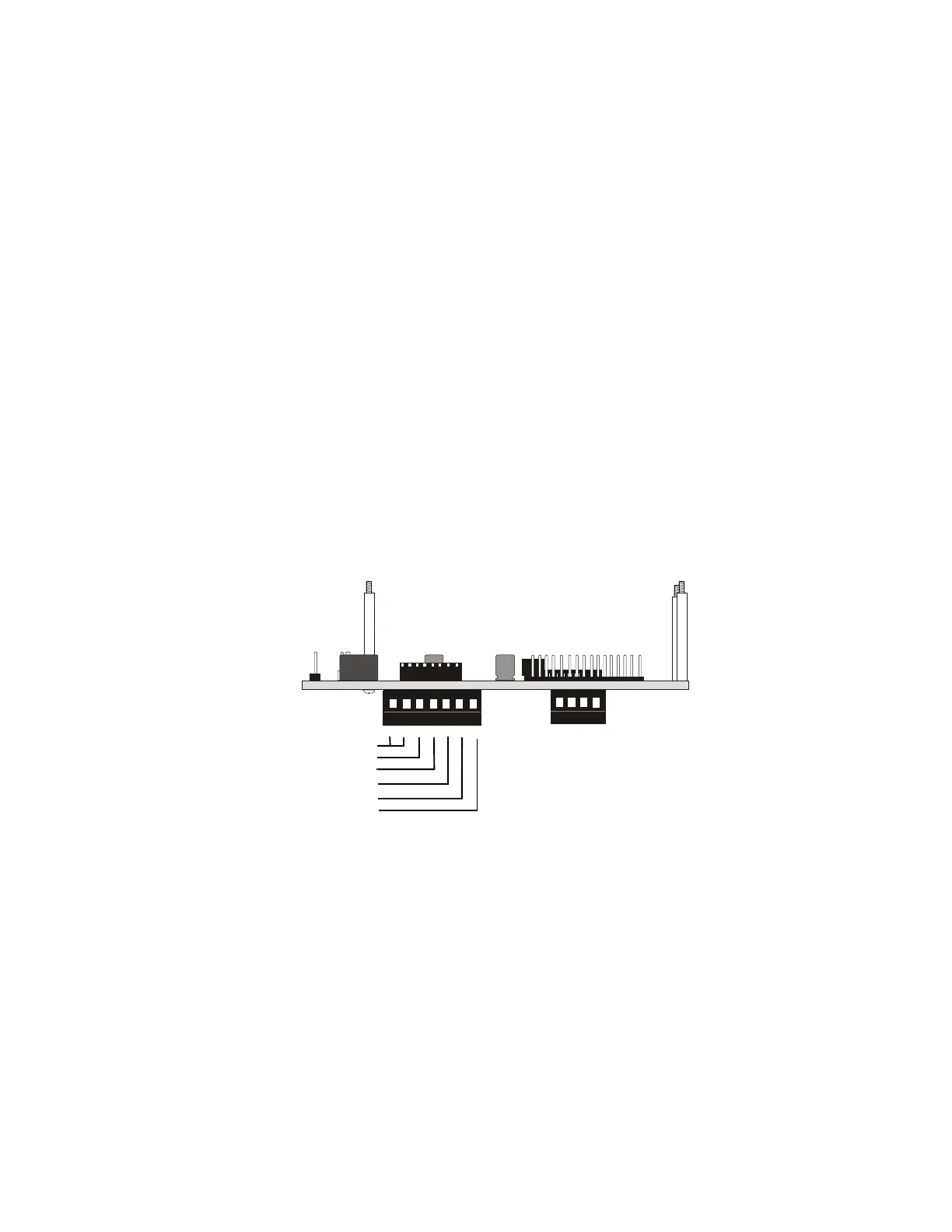
4 3 2 1
7 6 5 4 3 2 1
12345 6
78
Figure 4-1: Power Connection
FDU80Bds.cdr
P2
P1
no connection
+24 VDC IN
+24 VDC OUT
-24 VDC IN
-24 VDC OUT
Earth Ground Option
FDU-80
www.PDF-Zoo.com