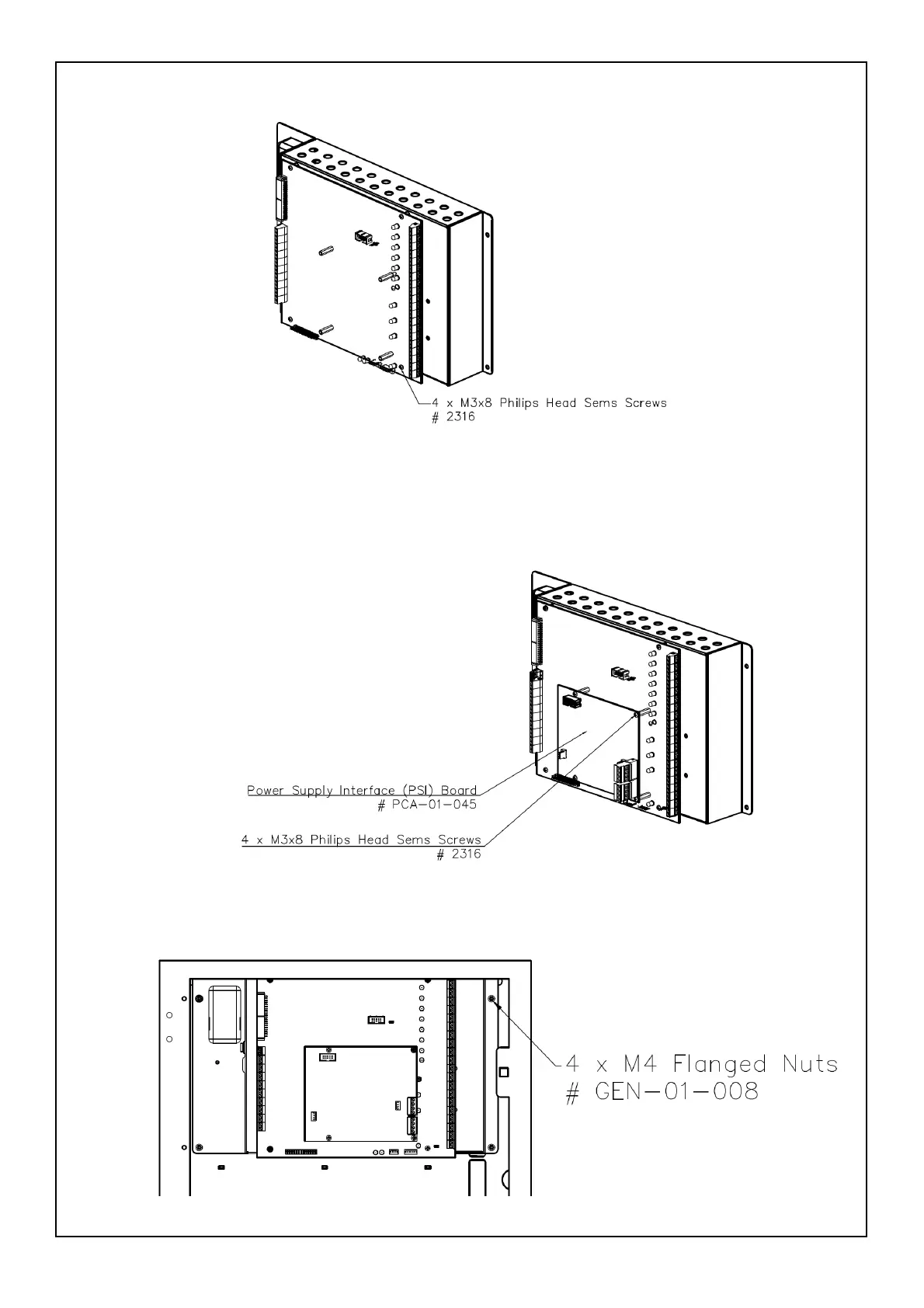
2. Attach the Termination board (#PCA-01-048) to the four Studs on the IFS-2600 chassis and secure it using
four Philips head sems screws (#2316) as shown in figure 3.
Figure 3, Termination Board Secured to IFS-2600 Chassis
3. Place the Power Supply Interface (PSI) board (#PCA-01-045) on the spacers (provided on the termination
board) and secure it using four Philips head sems screws (#2316) as shown in figure 4.
Note: This assembly is termed as Top Hat Assembly, which will be secured to the Base panel.
Figure 4, PSI Board attached to Termination Board
4. If the IFS-2600 Top Hat Assembly was removed from the panel, re-attach it to the top location of IFS-2600
Base panel and secure it using four M4 flanged nuts (GEN-01-008) as shown in figure 5.
Figure 5, IFS-2600 TB on Chassis installed in Base Panel
 Loading...


