Do you have a question about the Notifier NBG-12LX and is the answer not in the manual?
Specifies voltage, current, temperature, and humidity ranges for the NBG-12LX.
Details on connecting the NBG-12LX to the FACP SLC and subsequent devices.
Explains how to activate the pull station and the reset procedure.
Steps to reattach the pull station door to the backplate.
Adherence to NFPA, local codes, and ADA compliance for installation.
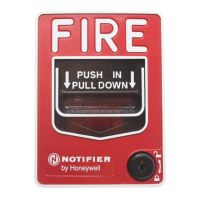
The NBG-12LX is a sophisticated, non-coded, dual-action manual pull station designed for use in fire alarm systems. Its primary function is to initiate an alarm by providing an addressable input to compatible Notifier intelligent control panels. This device is engineered to integrate seamlessly into modern fire detection systems, offering both reliability and ease of use.
At its core, the NBG-12LX operates on a dual-action mechanism, requiring two distinct steps to activate an alarm. Users must first push in the handle and then pull it down. This dual-action design helps to prevent accidental alarms, ensuring that an alarm is only initiated when there is a deliberate intent to do so. Once activated, the pull station clearly displays the word 'ACTIVATED' on the top of its handle, providing immediate visual confirmation of its status.
A key feature of the NBG-12LX is its addressable module, which is housed internally within the pull station. This module allows the device to communicate its unique address to the fire alarm control panel, enabling precise identification of the alarm's origin. The pull station is designed to be compatible with all Notifier intelligent panels and can automatically operate in either FlashScan™ or CLIP (Classic Loop Interface Protocol) mode. FlashScan™ is a patented high-speed communications protocol that enhances the efficiency and speed of data transmission within the fire alarm system. The operating mode (FlashScan™ or CLIP) is typically selected at the FACP, though for panels that do not support FlashScan™, CLIP mode is enabled by default. No specific selection is required at the pull station itself, simplifying installation and configuration.
The NBG-12LX is built to meet ADA (Americans with Disabilities Act) requirements, ensuring accessibility for all users. It requires a maximum pull force of 5 pounds to activate, making it easy to operate for individuals with varying physical abilities. The operating instructions are not only molded directly into the pull station handle but are also accompanied by Braille text, further enhancing accessibility. Additionally, molded terminal numbers are present, aiding in correct wiring during installation.
For installation, the NBG-12LX offers flexibility. It can be surface mounted using a Notifier SB-10 surface backbox or semi-flush mounted into standard single-gang, double-gang, or 4-inch square electrical boxes. An optional BG-TR trim ring is available for semi-flush mounting applications, providing a clean and finished appearance. The wiring process is straightforward, with clear instructions provided for connecting the Signaling Line Circuit (SLC) to the pull station's terminals. Polarity is crucial for this connection and must be observed carefully. The device's address is set by turning rotary address switches located on the internal addressable module. Each device must have a unique address, and this address should be recorded on the product ID label inside the pull station for future reference.
Resetting the NBG-12LX after an alarm requires a key-lock reset feature. To reset, a key must be inserted and turned counterclockwise. This action allows the door to be opened, which in turn moves the handle back into its 'NORMAL' position. Closing and locking the door automatically resets the alarm switch. It's important to note that simply opening the pull station door will not activate or deactivate the alarm switch, preventing unintended alarms during maintenance or inspection.
Maintenance of the NBG-12LX involves ensuring proper installation and regular testing. The manual emphasizes the importance of installing the device in accordance with all applicable NFPA standards, national and local Fire and Electrical codes, and the requirements of the Authority Having Jurisdiction (AHJ). Regular testing of the devices is also crucial to ensure they function correctly and report alarm conditions as expected. Failure to adhere to these guidelines could result in the device not reporting an alarm condition, for which Notifier is not responsible if the devices are improperly installed, tested, or maintained.
The design also includes practical considerations for assembly. If the pull station door becomes detached during mounting, a specific procedure is outlined to reattach it to the backplate. This involves aligning the door and backplate in a full open position, bringing the door behind the backplate, aligning hinge posts and holes, sliding the holes onto the posts, and then slightly closing the door to lock the two pieces together. This detailed procedure ensures that the device can be properly reassembled without damage.
In summary, the NBG-12LX is a robust and user-friendly addressable manual pull station that combines advanced communication capabilities with a focus on accessibility and reliability. Its dual-action activation, addressable module, ADA compliance, and straightforward maintenance procedures make it a valuable component in any modern fire alarm system.
| Material | Polycarbonate (PC) |
|---|---|
| Product color | Red |
| Connectivity technology | Wired |
| Input voltage | 24 V |
| Power source type | DC |
| Operating temperature (T-T) | 0 - 49 °C |
| Operating relative humidity (H-H) | 10 - 93 % |
| Package weight | 272.15 g |
|---|


 Loading...