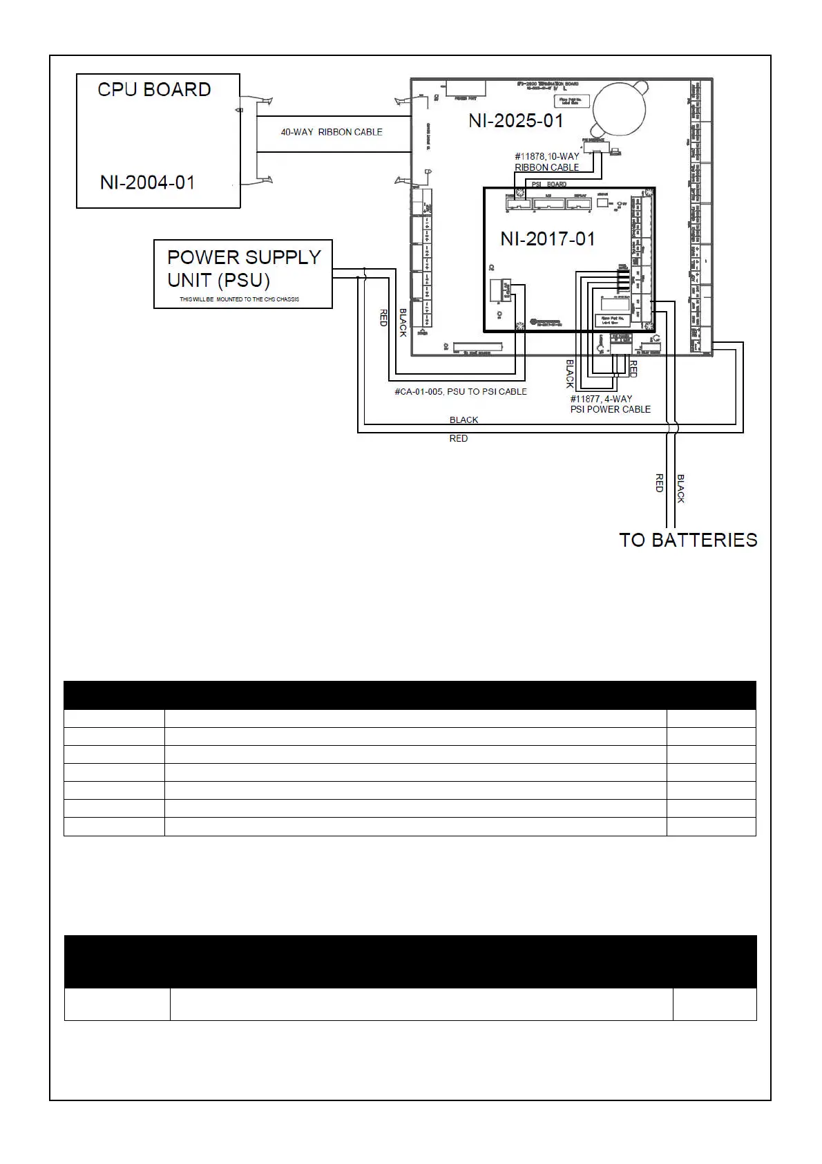
Figure 6, Termination Board, PSI & PSU Connection Diagram
3. Components
The IFS-2600 TB kit assembly contains the following components, as outlined in Table 1.
Part No. Description Qty
2316 M3 x 8 Philips Head Sems Screws 8
10313 M3 Flanged Nuts 4
11164 M3 x 20 M/F Hexagonal Tapped Spacer 4
11877 Cable - 4 way Power PSI for IFS-2600 – 150mm (DWG0058) 1
11878 PSI-FIM Ribbon Cable10 Way – 150mm (DWG0059) 1
CA-01-005 24V Cable – PSI to PSU – 4 Way, Red+Black 550mm (DWG0304) 1
PCA-01-048 Termination Board to Suit IFS-2600, NI-2025-01 PCB 1
Table 1: Components
4. Supplemental Documentation
information
on...
Refer to... Part No.
IFS-2600 TB IFS-2600 Installation, Programming & Operations Manual DOC-01-009
Table 2: Supplemental Documentation
 Loading...


