30 NFS-320/E/C Installation Manual — P/N 52745:M2 7/1/14
Installation Installing EIA-485 Devices
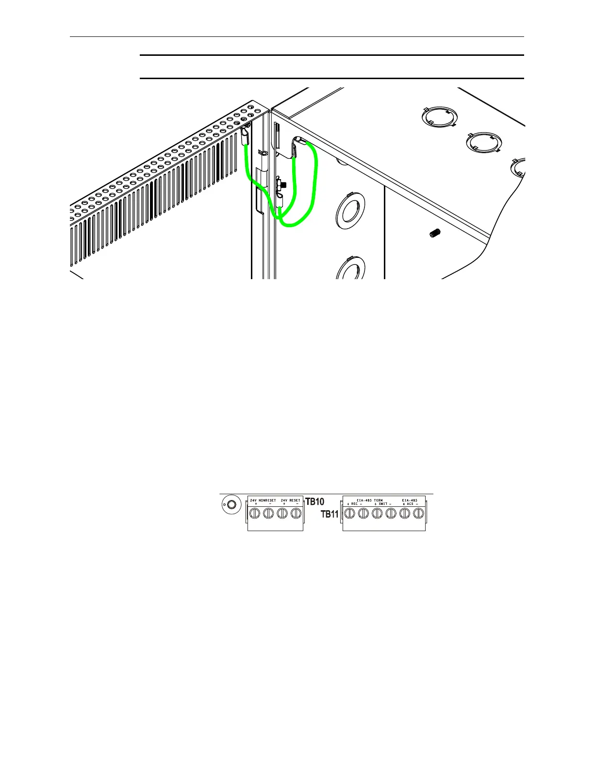
NOTE: In order to meet UL wiring requirements, please install grounding straps as shown below.
3.9.1 Labeling Modules and Circuits
At the time of installation, each nonpower-limited circuit connected to ACM-8R, and LDM-R32
modules must be identified in the space provided on the cabinet door label when connected to a
non-power-limited source of power.
The label lists all compatible power-limited modules and circuits; also see Figure 2.2 on page 13.
The LDM-R32 is power-limited only when connected to power-limited sources. When connected
to a non-power-limited source, the power-limited marking must be removed.
3.10 Installing EIA-485 Devices
Figure 3.14 provides a closer view of the EIA-485 connections provided on TB11. Because specific
connections can vary by the type of device being connected, refer to the product installation manual
for details.
Figure 3.14 EIA-485 Connections
3.11 Installing Remote Printers and/or CRT
3.11.1 Custom Cable Fabrication
A custom cable needs to be fabricated to connect the PRN Printer or the CRT-2 Monitor to the
system. Length of the cable will vary with each installation, but should not exceed a maximum
length of 20 feet (6.1 m). Printer must be installed in the same room as the panel, and the cable be
installed in conduit. Construct cable as follows:
1. Using overall foil/braided-shield twisted-pair cable, properly connect one end to the DB-25
Connector using the wiring specifications shown in the table below. (Custom cable kit
P/N 90106 is provided.)