34 NFS-320/E/C Installation Manual — P/N 52745:M2 7/1/14
Installation Wiring a Signaling Line Circuit (SLC)
• Set Host/Printer=EIA/AUX.
• Set EIA Data Format=8/1/N.
• If the AUX device is a printer, set the Printer and AUX Data Format=7/1/E.
• If the AUX device is a second CRT-2, set the AUX Data Format=8/1/N.
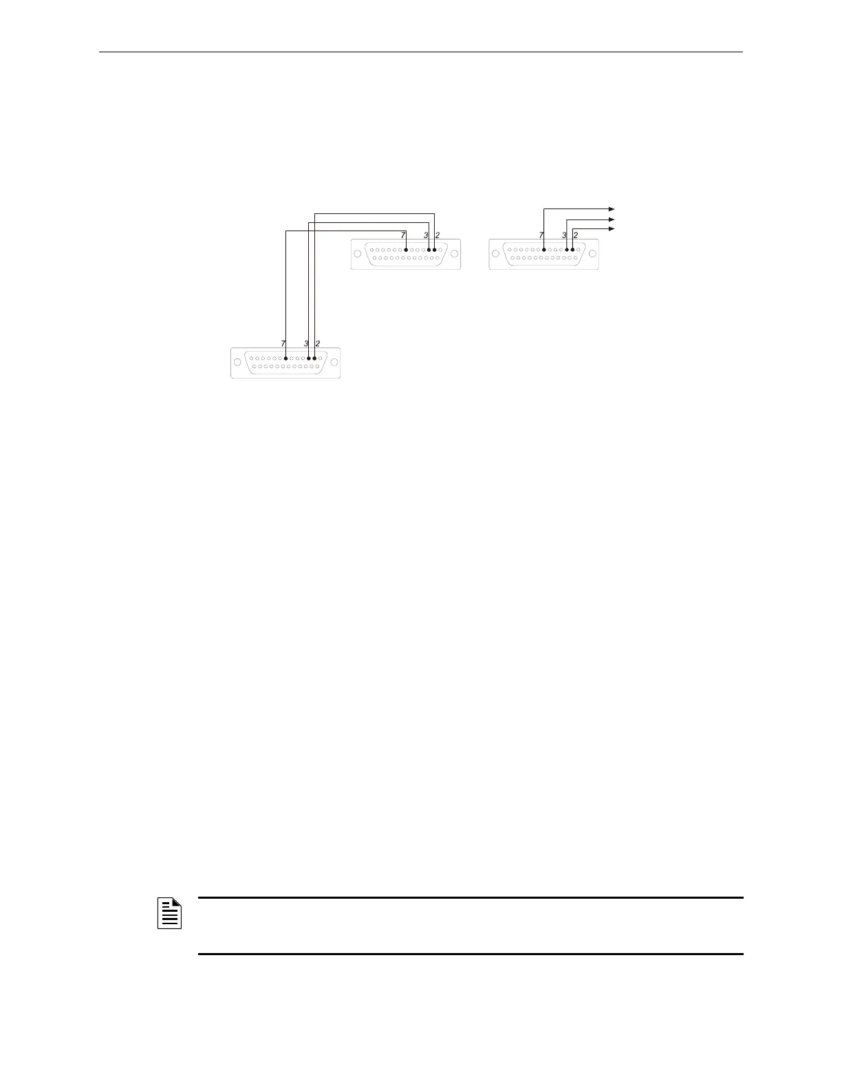
Connect multiple devices as shown in Figure 3.17.
3.12 Wiring a Signaling Line Circuit (SLC)
Overview
Communication between the control panel and intelligent and addressable initiating, monitor, and
control devices takes place through a Signaling Line Circuit (SLC). You can wire an SLC to meet
the requirements of NFPA Style 4, Style 6, or Style 7 circuits.
This manual provides requirements and performance details specific to this control panel; for
installation information and general information, refer to the SLC Wiring Manual.
Wiring
Maximum wiring distance of an SLC using 12 AWG (3.31 mm
2
) wire is 12,500 feet (3810 meters)
total twisted-pair for Style 4, Style 6 and Style 7 circuits.
Capacity
The NFS-320/E/C provides one (1) SLC, with a total capacity of 318 intelligent/addressable
devices:
• 01-159 intelligent detectors
• 01-159 monitor and control modules
Units employing multiple detector operation shall include a minimum of two detectors in each
protected space and reduce the detector installation spacing to 0.7 times the linear spacing in
accordance with National Fire Alarm Code, NFPA. For spacing requirements refer to the detector’s
installation instructions.
To Control Panel
TB12-PC/CRT REF
TB12-PC/CRT TX
TB12- PC/CRT RX
To EIA-232 port of CRT-2
(female socket shown)
To AUX Port of CRT-2
(female socket shown)
To EIA-232 port of next
CRT-2 or PRN (female socket shown)
prncrt-conn.cdr
Note: For wire requirements, see Table B.1 in Appendix B “Electrical Specifications”.
Figure 3.17 Connecting Multiple Devices on the EIA-232 Circuit
NOTE: To meet the ten-second response time required by UL 864, 9th edition, when SLC loops
are configured to run in CLIP mode, all input modules must be mapped to address 19 and lower.
There are no limits to detectors or output modules.