NFS-320/E/C Installation Manual — P/N 52745:M2 7/1/14 41
Fire/Security Applications Applications
For bypass of security zones, use the DISABLE routine (covered in the Status Change section of
the NFS-320/E/C Operations Manual) for Security type devices.
4.6.2 Installing a Security Tamper Switch
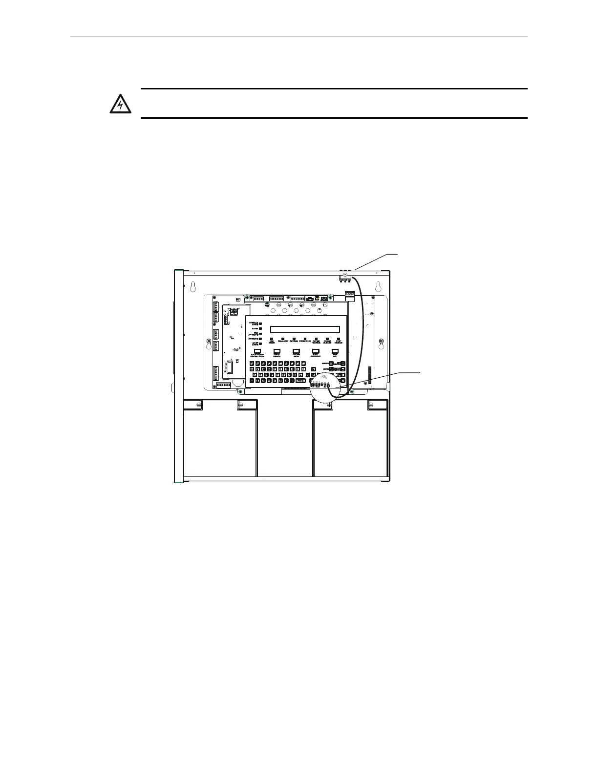
To wire the cabinet with a Security Tamper Switch kit model STS-200, refer to Figure 4.5:
1. Install the STS-200 Tamper Switch into the location shown in Figure 4.5. Push the switch
through the opening until it snaps into place.
2. Connect the STS-200 connector to J5 (Security Tamper) on the Control Panel. (As shown in
Figure 4.5, J5 is located on the circuit board, underneath the edge of KDM-R2.)
4.6.3 Receiving Unit
For applications requiring transmission of security alarm information to a central receiving unit, the
control panel may be connected via the UDACT or UDACT-2 to a compatible receiving unit (see
the UDACT Manual or UDACT-2 Manual). For information on configuring the Receiving unit for
Combination Fire/Security applications, refer to the documentation for that control panel.
4.6.4 Programming
The control panel can communicate with any number of security devices. To do so, program the
points as follows:
1. Select the address of the module(s) to be used for security.
WARNING:
Damage can result from incorrect wiring connections.
320_STS1.wmf
Connect to
J5 “Security Tamper”
STS-200 mounting
location
Figure 4.5 Installing the STS-200 Security Tamper Switch