NFN Web Server User’s Manual PN 51990:A2 12/02/03 15
2.4 NFN WEB SERVER PC BOARD LAYOUT
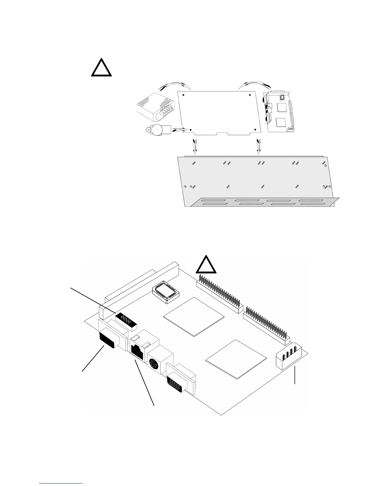
The PC board layout (P/N 46173) is shown in Figure 2.4-1 below. Descriptions of pertinent connections are described
in subsequent sections.
EIA-232 Port:
DB9-NUP connector - used
for operation as the network
connection to
NOTI•FIRE•NET™.
PC-PC connector - used for
configuration (cable sup-
plied by customer).
Figure 2.4-1: PC Board Layout
RJ45 Ethernet Connector
(CN2) (to PNET-1)
HDD Power Connector
(P1)
2.3 INSTALLING THE NFN WEB SERVER ASSEMBLY INTO A CAB-4 SERIES CABINET
This section describes the installation of the NFN Web Server Assembly into a CAB-3/CAB-4 series cabinet.
Figure 2.3-1: NFN Web Server Installation Diagram
1. The NFN Web Server, power supply
and PNET-1 surge suppressor are
installed onto the mounting plate. The
Web Server board uses four standoffs,
the power supply uses two screws, and
the PNET-1 uses one.
2. The mounting plate is installed
onto the CHS-4(L).
3. The CHS-4(L) is
installed into the CAB-3 or
CAB-4 series cabinet.
!
NOTE: Cabinet is ordered separately. For installation details,
refer to the CAB-3/CAB-4 Series Installation Document, 15330.
NOTE: The replacement of the lithium battery
of the GENE-4310 CPU Board is to be
performed by a trained technician.
!
Modem connector (J5)
www.PDF-Zoo.com