NFN Gateway PC Configuration About the Network Interface Card Installation
14 NFN Gateway Installation & Operation Manual - P/N: 52307:Rev: D 06/01/07
2.2.1 Network Interface Card Layout
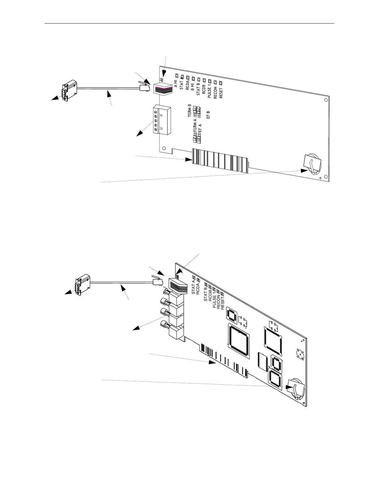
Figure 2.1 NFN-GW-PC-W Card Layout
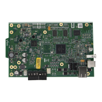
Figure 2.2 NFN-GW-PC-F Card Layout
1
0
1
0
Connect cable to the EIA-232
connector (J2) on the network card.
This PC board is shipped with a shunt plug over the UPS
SUPV pins. Remove the shunt to write for UPS supervision.
Connector Cable
(P/N 75557)
NFN Network
Connection
Edge Connector (J5)
insert into a vacant PCI
slot on the Workstation.
Battery
(P/N LITHBATT-3V)
Note:
The NCS-NCW/F is shipped with a paper
strip between the clip and battery. Remove
the paper strip before powering.
Connect cable to an
available COM port
on the Workstation.
RX B
TX B
RX A
TX A
Connect cable to the EIA-232
connector (J2) on the network card.
This PC board is shipped with a shunt plug
over the UPS SUPV pins. Remove the
shunt to write for UPS supervision.
Connector Cable
(P/N 75557)
NFN Network
Connection
Edge Connector
(J5) insert into a
vacant PCI slot on
the Workstation.
Battery
(P/N LITHBATT-3V)
Note:
The NCS-NCW/F is shipped with a
paper strip between the clip and
battery. Remove the paper strip
before powering.
Connect cable to
an available
COM port on the
Workstation.