ML0021 August 15, 2018
140 Copyright 2018 Bitronics, LLC
Example 1. Discrete Digital I/O:
Please refer to Figure A1 for wiring, Figure A2 through A4 for configuration, and Figure 11,
section 9.9 for the pin-out of the Digital I/O cards and internal resistor values that are not
shown in Figure A1.
Note: Standard Digital I/O cards (P30A and P31) incorporate an internal parallel current
path on all digital outputs which conducts through a resistance even when the output
contacts are open. This is normally used as a parallel digital input circuit but it makes the
standard card unsuitable for cross-triggering because it tends to pull-up the switched
conductor when contacts are open. To use cross-triggering as shown in this example,
be sure to specify optional P30AW (8-point) and P31W (16-point) Digital I/O cards
when ordering M87x models.
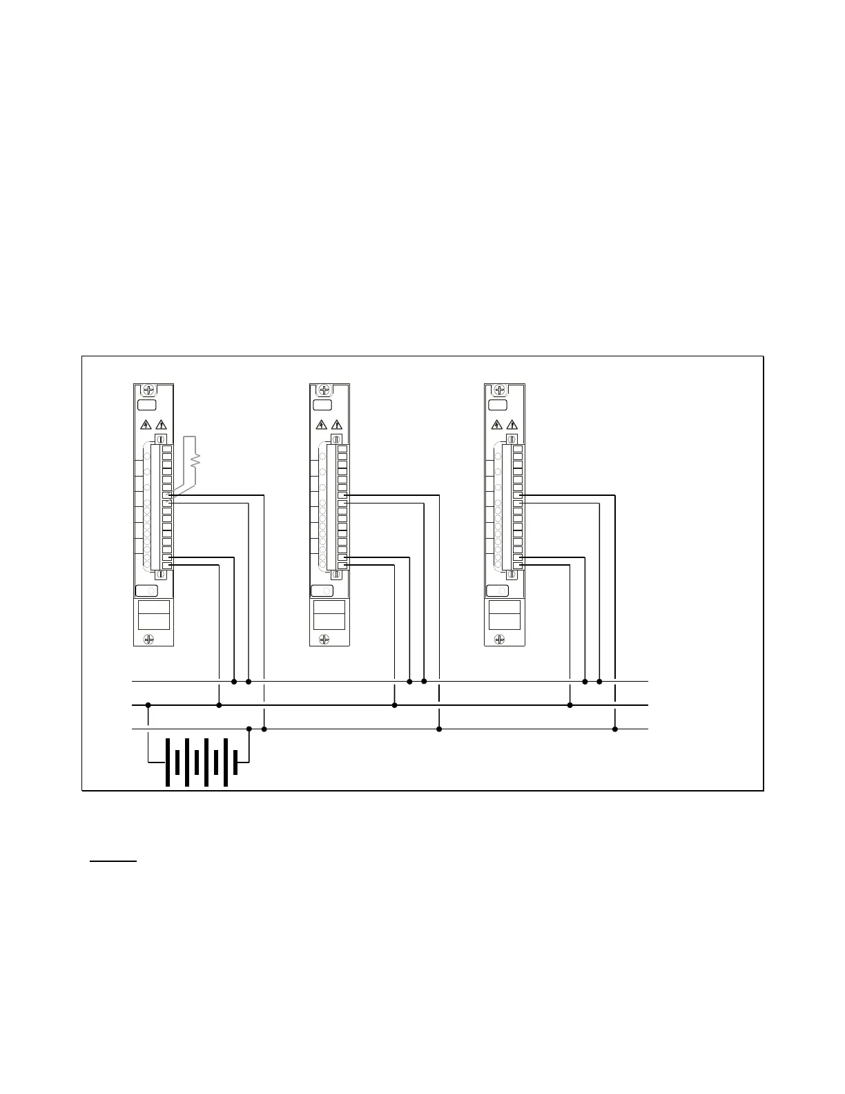
Figure A 1
Wiring:
Figure A1 illustrates one digital output (lower pair, pins 1 and 2 on a P30AW card) from
each of three M871 units wired in parallel. Closing the Output 1 contact on any M871 will
energize the switched conductor. The upper pair, pins 9 and 10, are digital inputs wired in
parallel between the switched and negative conductors. All three units will sense a status
change on Input 5 whenever the switched conductor is energized or de-energized. All
digital inputs on the M871 incorporate an internal current limiting resistor so no external
-P30
HS
IN
O
IN
O
IN
O
IN
O
-P30
HS
IN
O
IN
O
IN
O
IN
O
-P30
HS
IN
O
IN
O
IN
O
IN
O
-
Switched
+
P30 Digital I/O Cards
from three different
Unit Unit Unit
R
P
o
tional