ML0021 August 15, 2018
141 Copyright 2018 Bitronics, LLC
resistor is required to prevent shorting (+) to (-) when digital outputs operate. It may be
advisable, however, to place one pull-down resistor (R
P
, in Figure A1) between the
switched and negative conductors to prevent chatter on the inputs. Acceptable values for
R
P
depend on the application, but something in the 100kΩ to 500kΩ range should
generally be safe in most cases.
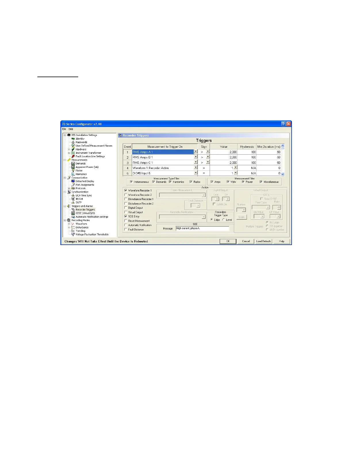
Configuration:
Figure A2 illustrates a typical configuration that will initiate an oscillography recording and
an SOE Log entry when the current exceeds a threshold on any of the three phases.
Figure A 2
Since a high current on one feeder would not normally be sensed by any other IEDs in a
substation, a cross-trigger is necessary to initiate the oscillography recorders on all other
IEDs. Figure A3 shows how any condition that triggers Waveform Recorder 1 also
operates Digital Output 1 which initiates the cross-trigger. In this example, the contact
dwells in the closed position for the length of time that Waveform Recorder 1 is running.
(The characteristics of WR1 are set on a different page of the 70 Series Configurator.)