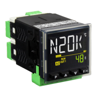
Controller N2000
NOVUS AUTOMATION 2/11
The function to be used in each channel of I/O is defined by the user
in accordance with the options shown in the Table 2.
I/O FUNCTION I/O TYPE CODE
No function -
LDB Output - Loop break detection Output
Control Output (Relay or Digital Pulse) Output
Automatic/Man mode change Digital Input
Run/Stop mode change Digital Input
Selected Remote SP Digital Input
Freezes program execution Digital Input
Program 1 selection Digital Input
0 to 20 mA analog control output Analog Output
4 to 20 mA analog control output Analog Output
0 to 20 mA PV retransmission Analog Output
4 to 20 mA PV retransmission Analog Output
0 to 20 mA SP retransmission Analog Output
4 to 20 mA SP retransmission Analog Output
Table 2 - I/O channel functions
The description for the functions follows:
•
- No function.
The I/O channel programmed with code 0 will not be used by the
controller. It is available to be used by serial communication as digital
output.
•
- Alarm output.
Available for all I/O channels. The selected channel can be used as
output to Alarms 1 to 4.
•
– Loop Break Detector function.
Assigns the output of the Loop Break Detector alarm to an I/O
channel. Available to all I/O channels.
•
- PWM control output.
Defines the channel to be used as control output (relay or digital
pulse). Available for all the channels. The digital pulse is available
on (when available) I/O5 and I/O6.
•
- Digital input with Auto/Manual function.
Defines the channel as Digital Input with the function of switching the
control mode between Automatic and Manual. Available for I/O5,
I/O6 and key .
Closed: Manual control /no
Opened: Automatic control /YES
•
- Digital input - Standard for I/O5, I/O6 and key. Start/Stop
input (“
”: YES / no).
Closed: outputs enabled/ YES
Opened: outputs disabled/ no
•
- Digital input - Standard for I/O5, I/O6 and key.
Closed: remote SP (4-20 mA in remote SP input)
Opened: main SP (internal programmed SV)
•
- Digital input - Standard for I/O5, I/O6 and key.
Opened: enables R&S program
Closed: holds R&S program (the program resumes when the contact
is opened again)
Closed Contact: Enables execution of the program
Opened Contact: Interrupts execution of the program
Note: Even when the execution of the program is interrupted,
the control output remains active and controlling the process at
the point (Setpoint) of interruption. The program will resume its
normal execution starting from this same point when the digital
input is closed.
•
- Digital input - Standard for I/O5, I/O6 and key. Selects
R&S program 1. Used to alternate between the main Setpoint and
a second Setpoint defined by the R&S program 1.
Closed: selects program 1
Opened: uses main Setpoint
•
- 0-20 mA and 4-20 mA Control Output.
Available for I/O 5 only, defines the channel as a 0-20 mA and 4-20 mA
control output.
•
- 0-20 mA and 4-20 mA PV retransmissions.
Available for I/O 5 only, configures the channel to retransmit the PV
measurement in 0-20 mA and 4-20 mA.
•
- 0-20 mA and 4-20 mA SP (Setpoint)
retransmissions.
Available for I/O 5 only, configures the channel to retransmit the
values of SP in 0-20 mA and 4-20 mA.
ALARMS FUNCTIONS
The controller has 4 independent alarms. They can be programmed
to operate with eight different functions, represented in Table 3.
•
– Sensor break alarm
It is activated whenever the input sensor is broken or disconnected.
•
– Ramp & soak program event alarm
This alarm is activated by the Ramp & Soak program (refer to the
PROGRAMS OF RAMP AND SOAK section on how to set the event
alarm).
•
– Alarm of Absolute Minimum Value
It is activated when the measured value is below the value defined in
the alarm Setpoint.
•
– Alarm of Absolute Maximum Value
It is activated when the measured value is above the value defined in
the alarm Setpoint.
•
– Alarm of Differential Value
In this function, the parameters “
”
represent the PV deviation as compared to the main SP.
Using the Alarm 1 as example: for Positive SPA1 values, the
differential alarm will be triggered when the PV value is out of the
range defined in:
(SP –SPA1) to (SP + SPA1)
For a negative SPA1 value, the differential alarm will be triggered
when the PV value is within the range defined above
•
– Alarm of Minimum Differential Value
It is activated when the PV value is below the value defined in:
(SP –SPA1)
Using the Alarm 1 as example.
•
– Alarm of Maximum Differential Value
It is activated when the PV value is above the value defined in:
(SP + SPA1)
Using the Alarm 1 as example.
 Loading...