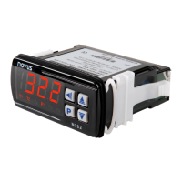
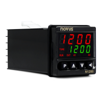
Controller N2000
NOVUS AUTOMATION 5/11
Fig. 4a – Connection of 4-20 mA Fig. 4b – Connection of 5 Vdc
• 4-20 mA
Refer to Fig. 4a. (The controller provides an internal electronic shunt
for the input current. No changes in the circuit are necessary).
• 0-5 Vdc:
Refer to Figure 4b for connecting voltage signals.
• 4-20 mA:
The connections for current signals 4-20 mA must be carried-out
according to Figure 4c.
4-20 mA transmitter using the N2000 24 Vdc supply
• Remote setpoint
The remote Setpoint (SP) is enabled by an external digital signal in
either I/O5 or I/O6, when programmed with the code
(Select
remote SP input).
An external resistor shunt of 100 Ω is required between the terminals
19 and 20.
(0-20 / 4-20 mA)
DIGITAL OUTPUT
I/O5 can also be configured as digital output. An example of usage is
shown in Fig. 5. I/O5 is electrically isolated from the sensor input.
Fig. 5 – I/O5 with output pulse for SSR.
DIGITAL INPUT
I/O5 and I/O6 can be used as digital inputs, accepting either dry contact
or NPN open collector signals. Fig. 6 shows a switch driving the I/O5
digital input. The digital input at I/O6 is driven only by dry contact
signals. Fig. 7 shows a typical digital input wiring for I/O6.
Fig. 6 – Digital input at I/O5 Fig. 7 – Digital input at I/O6
OPERATION
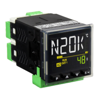
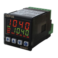
The front panel is shown in Fig. 8.
Fig. 8 - Front panel parts
Status display/PV: shows the value of PV (Process Variable). When
in programming mode, shows the parameter name.
Parameter display/SV: shows the SV (Setpoint Variable) value and
the value of other parameters of the controller.
COM Indicator: Flashes when communication messages are sent by
the controller.
TUNE Indicator: Lights during the execution of PID automatic tuning.
MAN Indicator: Lights when the controller is in manual.
RUN Indicator: Lights when the controller is active, with control and
alarm outputs enabled.
OUT Indicator: For relay or pulse control output, reflects the actual
state of the output. If an analog output is assigned for control, lights
continuously.
A1, A2, A3 and A4 Indicators: Status of the alarms.
- PROG key: used to walk through the menu cycles
- BACK key: go back to the previous displayed parameter
- DECREASE keys: Used to change
parameter values
-
AUTO/MAN KEY: Shortcut for automatic/manual control
selection. Alternates the control mode between automatic and
manual each time the key is pressed.
-
PROGRAMMABLE FUNCTION KEY: Can be assigned to the
special functions described for the
according to Table 2.
When the controller is turned on, its firmware version is displayed for
3 seconds, after which the controller starts normal operation. The
values of PV and SV are displayed and the outputs are enabled.
Before the controller is ready to be used in a given process, it
requires some basic configuration, such as:
• Input type (T/C, Pt100, 4-20 mA).
• Control Setpoint Value (SP).
• Control Output Type (relays, 0-20 mA, 4-20 mA).
• PID parameters (or hysteresis for ON / OFF control)