NOVUS AUTOMATION 9/11
Table 5 shows the sequence of cycles and parameters presented in the indicator display. There are parameters that must be defined for each
alarm available.
OPERATION CYCLE
CYCLE
PROGRAMMING
CYCLE
ALARM CYCLE
CONFIGURATION
CYCLE
I/O CYCLE
Table 5 - All the controller parameter
RAMP AND SOAK PROFILE PROGRAM
This feature allows for the elaboration of a behavior profile for the
process. Each program is composed of a set of up to 7 segments,
named RAMP AND SOAK PROGRAM, defined by SP values and
time intervals.
When the program is defined and runs, the controller starts to
automatically generate the SP according to the program.
At the end of the program execution, the controller turns the control
output off (“
”= no).
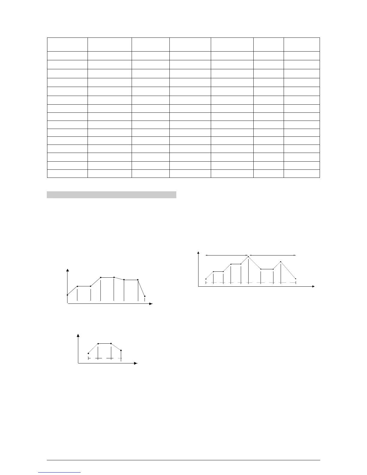
Up to 7 different profiles with 7 segments each can be
programmed. The figure below displays a profile model:
Fig. 9 - Example of a complete ramp and soak profile
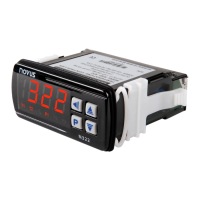
To execute a profile with fewer segments just program 0 (zero) for
the time intervals that follow the last segment to be executed.
Fig. 10 - Example of a profile with fewer segments. (T4 is set 0)
The program tolerance “
” defines the maximum deviation
between PV and SV for the execution of the profile. If this deviation is
exceeded, the program will be interrupted until the deviation falls to
within the tolerance band.
Programming 0 (zero) at this prompt disables the tolerance and the
profile execution will not to be halted even if PV does not follow SV
(time priority as opposed to SV priority).
The ramp and soak event function is used to activate alarms at any
segment of program 1. This applies only to program 1.
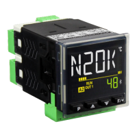
LINK OF PROGRAMS
It is possible to create a more complex program, with up to 49
segments, joining the seven programs. This way, at the end of a
program execution the controller immediately starts to run another one.
When a program is created, it must be defined in the “
" screen
whether there will be or not another program.
To make the controller run a given program or many programs
continuously, it is only necessary to link a program to itself or the last
program to the first.
Fig. 11 - Example of two linked programs
EVENT ALARM
To enable this event function the alarms to be activated must be
selected for
function and are programmed at the
prompts. The number to be programmed at the prompt defines the
alarms to be activated.
Note:
1- When recovering from power outage the controller resumes the
ramp and soak execution from the beginning of the interrupted
segment a ramp and soak program:
• Program the tolerance value, SP’s, time and event.
• If any event alarm is required program the ramp and soak event
function.
• Set the control mode to automatic.
• Enable program execution in “
“ screen.
• Start control at the
prompt by selecting YES.
Before executing the program the controller waits for PV to reach the
first set point
. Should any power failure occur the controller
resumes at the beginning of the segment it currently is.