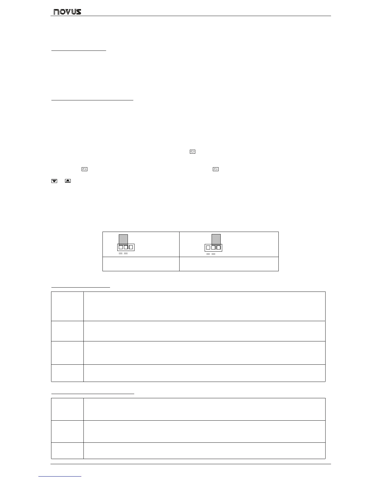
N480
4
Both outputs are available in the basic model and the desired main control output is user selected via keyboard (refer to “
Cntr
CntrCntr
Cntr “ prompt). The remaining output can then be used as an alarm output.
In case of sensor break or failure an error "Erro
ErroErro
Erro" message is displayed and the control output is turned off.
2.5 ALARM OUTPUTS
• Alarm Output 1: SPST relay 3A/250Vac or 5Vdc/20mA pulse
• Alarm Output 2: SPST relay 3A/250Vca (optional)
3. CONFIGURATION AND OPERATION
Prior to first operation the controller should be fully configured. The user must set basic parameters as temperature type
(“TYPE
TYPETYPE
TYPE”), the desired control set point (“ SP
SPSP
SP “), the alarms set points (“SPA1
SPA1SPA1
SPA1” and “SPA2
SPA2SPA2
SPA2”), etc.
3.1 PARAMETERS FLOW CHART
The programming parameters are organized in 4 different sets or levels:
• Operation level
• Alarms and tuning level
• Configuration level
• Calibration level
At power up the controller displays a prompt at the Operation Level and remains in this level while under normal operation.
The other levels are only accessed when a change of parameters is necessary (except for Set Point change). To reach
these other parameters the user must keep the INDEX Key (
) pressed for about three seconds. After this time the
controller will show the first parameter of the next level. By keeping the INDEX key pressed for another 3 seconds the next
level will be accessed.
Release the
key when the desired level is reached. Press once the
to go to the next prompt in the same level.
When a parameter is shown the display will alternate its name and value. The value can then be changed by pressing the
or
key.
After the last parameter in one level is reached the controller returns to operation level and the display will indicate the
measured temperature.
The display will also go back to the measured temperature whenever the display is inactive for 20 seconds or more.
When a parameter value is changed via keyboard the controller will only accept the new value after the user presses the
INDEX key to go to next prompt or if the keyboard is left inactive for 20 seconds.
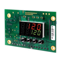
For disabling the keyboard, move the internal strap to the position KEY DISABLE. All parameters will be protected, accept
the SP parameter.
KEY
DISABLE
KEY
DISABLE
igure 2 – Strap in normal operating
position (enabled)
Figura 3 – Strap position for inhibiting the
keyboard
3.2 OPERATION LEVEL
TEMPERATURE
INDICATION
END
SP
Set Point
TEMPERATURE measured by the sensor.
At power up, the upper display shows the process temperature value. It also shows the messages
described in chapter 5 of this manual.
The lower displays shows the set point value which is the temperature value desired for the process.
rAte
rAtE
TEMPERATURE RATE OF RISE: The user defines the rate of temperature rise from the starting
temperature to the value set in “ SP
SPSP
SP ”.
Rate is defined in °C / minute.
T Sp
time for
soak
TIME FOR SOAK: Time in minutes which the temperature will remain at the selected “ SP
SPSP
SP “. Refer to
item 4.
Rvn
run
RUN: At this prompt the user sets the control output and alarms to active or to inactive.
0
00
0 - inactive outputs; 1
11
1 - active outputs;
3.3 TUNING AND ALARMS LEVEL
Atvn
Auto tune
AUTO-TUNE: Activates the auto-tuning of PID parameters.
0
00
0 - Auto-tune is off;
1
11
1 - Auto-tune is on;
Pb
Proportional
band
PROPORTIONAL BAND: percentage of maximum input span.
When set ot zero (0), control action is ON/OFF.
Ir
integral rate
INTEGRAL RATE: Integral time constant in repetitions per minute (Reset). This constant is not used
when controller is set to ON/OFF action (Pb=0).