32
420012001500 - 03182024 - Rev. 04
NOTE: In piping applications utilizing a single
zone, it is recommended that the installer
use flow / check valves with weighted seats
at or near the appliance to prevent gravity
circulation.
NOTES:
1. This drawing is meant to show
system piping concept only. Installer
is responsible for all equipment and
detailing required by local codes.
2. All closely spaced tees shall be within 4
pipe diameters center to center spacing.
3. A minimum of 6 pipe diameters of
straight pipe shall be installed upstream
and downstream of all closely spaced
tees.
4. The minimum pipe size of DHW piping
should be ¾” diameter and CH piping
should be 1” in diameter.
5. Circulators are shown with isolation
flanges. The alternative is standard
flanges with full port ball valves. Purge
valves can be used with circulator flanges
as an alternative.
The piping will not support the weight
of the circulators. Refer to the circulator
manufacturer’s instructions to properly
support the circulator. Failure to comply with
these instructions could result in property
damage, severe personal injury, or death.
WARNING
Part 4 - Water Piping
CAP WHEN
NOT IN USE
JUMPER
JUMPER
CLOSELY SPACED TEES
M
INDIRECT FIRED
WATER HEATER
ZONE 1 ZONE 2
CH PUMP
N LG
DHW PUMP
N LG
120VAC INPUT
N LG
LINE VOLTAGE JUNCTION BOX
ZONE
#1
ZONE
#2
MAKE-UP
WATER
WHT WHT
GNDGND
BLK BLK
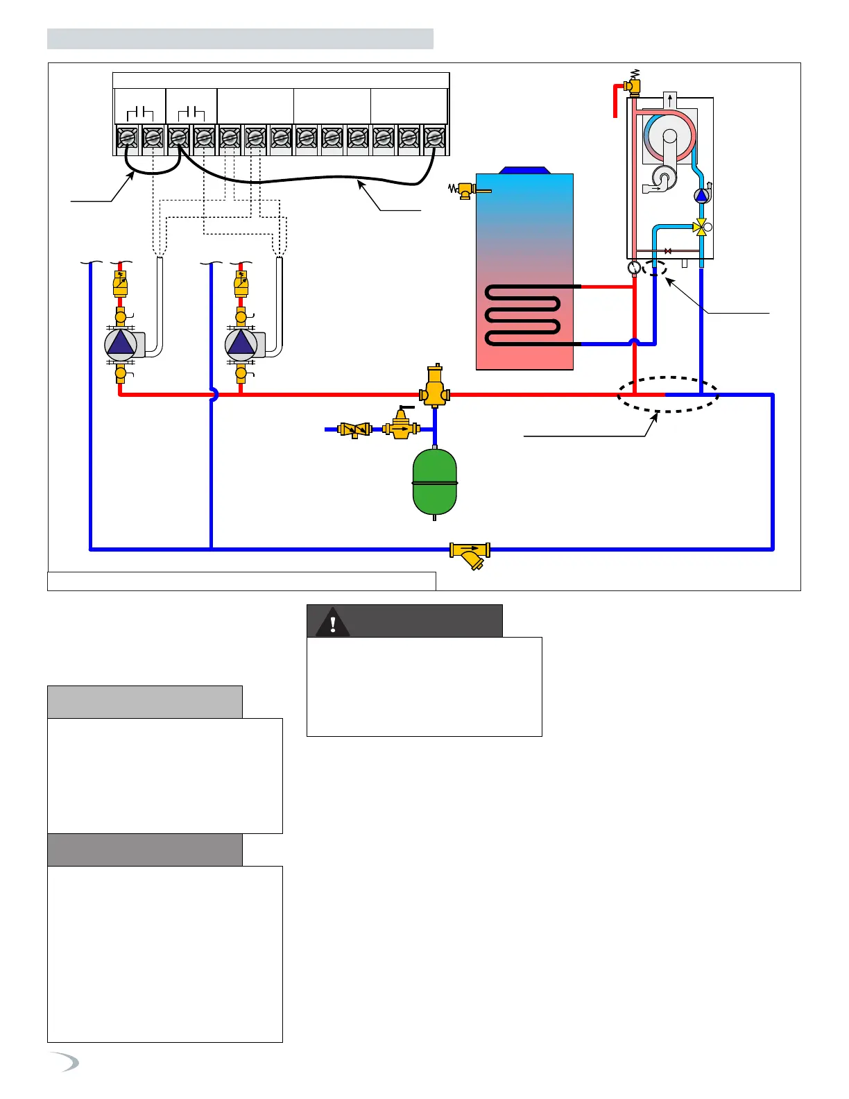
Figure 25 - TRX085 / TRX120 with Multiple Central Heating Circulators
6. Piping shown is Primary/Secondary, and
is mandatory.
7. Install a minimum of 12 diameters of
straight pipe upstream of all circulators.
8. VERY IMPORTANT – Minimum flow rates
outlined in this manual (2 gpm) must be
maintained through the heat exchanger
to minimize short cycling.
9. In a valve-based system, each heating
zone has a zone valve which opens
when that zone calls for heat. Each zone
thermostat is wired to its corresponding
zone valve. Contacts in the zone valves
provide a signal to the boiler to operate
when there is a call for heat.
10. Unit is equipped with built-in primary
pump. This pump is sized to ensure
proper flow rate through the boiler heat
exchanger and related piping.
11. IWH Applications - a mixing valve is
recommended if the DHW temperature is
set above the factory setting of 119
o
F.
On
TRX085 / TRX120
Models Only.
If the boiler’s DHW connection is not
used, cap the fitting as indicated above.
A
cap is included with the boiler.
Further,
set parameter 2.10.8 (CH forced diverter
position) = 1 from the DHW Setup ->
Advanced Menu, to lock the 3-way valve
in the central heating position. Failure to
lock the valve in the central heating position
may prevent the boiler from delivering heat,
which could result in property damage.
CAUTION
NOTICE
Figure illustrates the basic plumbing
requirements for a TRX085 / TRX120 boiler
installation utilizing Primary/Secondary
piping when the boiler circulator will not
provide adequate flow for the system.
Primary / Secondary is required to provide
adequate flow for the secondary circuits.
 Loading...


