42
420012001500 - 03182024 - Rev. 04
Part 5 - Venting
H. Applications
1. Direct Vent Installation of Exhaust and Intake
If installing a direct vent option, combustion air must be drawn
from the outdoors directly into the boiler intake, and exhaust must
terminate outside. There are three basic direct vent options detailed in
this manual:
1. Side Wall Venting,
2. Roof Venting, and
3. Unbalanced Venting.
Be sure to locate the boiler such that the exhaust vent and intake
pipe can be routed through the building and properly terminated.
Different vent terminals can be used to simplify and eliminate multiple
penetrations in the building structure (see Optional Equipment in
Venting Section). The exhaust vent and intake pipe lengths, routing
and termination methods must all comply with the methods and
limits given in the Venting section of this manual.
When installing a combustion air intake from outdoors, care must be
taken to utilize uncontaminated combustion air.
NOTE: To prevent combustion air contamination, see Table 7.
All vent pipes must be glued, properly supported, and the exhaust
pitched a minimum of 1/4” per foot back to the boiler to allow
drainage of condensate. When placing support brackets on vent
piping, the first bracket must be within 1 foot of the boiler and the
balance of 4 foot intervals on the vent pipe. Venting must be readily
accessible for visual inspection from the first three feet from the boiler.
Take extra precaution to adequately support the weight of vent pipes
terminating through the roof. Failure to properly support roof terminated
piping could result in property damage, serious injury, or death.
WARNING
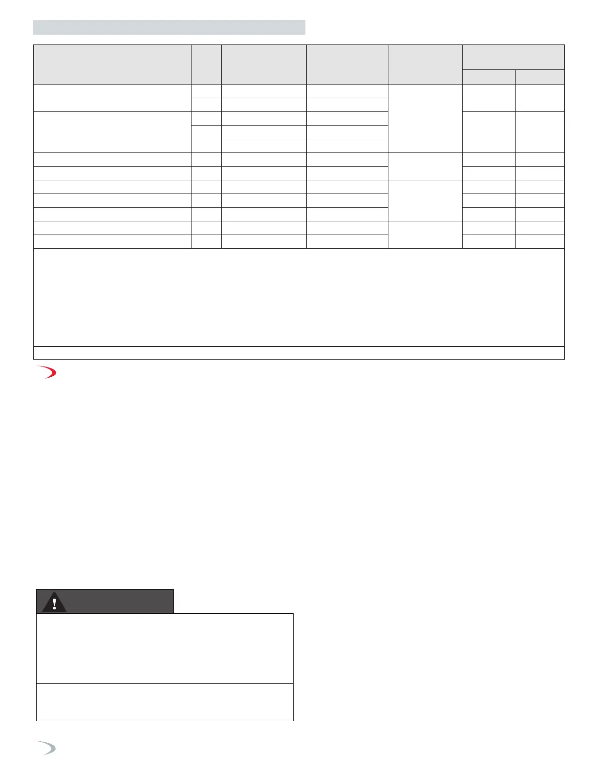
Description
Vent
Size
Supplier
Part Number
Figure
Vent Material
Compatibility
Vent Option
Availability
Roof Wall
IPEX Low Profile
(Wall)
7
2” 196984 (NTI p/n 85062) 36, 40
PVC/CPVC
No Yes
3” 196985 (NTI p/n 84357) 36, 40
IPEX Concentric
(Wall/Roof)
4, 5, 6, 7
2” 196125 37, 41, 48, 52
Yes Yes
3”
196116 (NTI p/n 84634) 37, 41, 48, 52
196117 37, 41, 48, 52
Duravent Polypro® Concentric (Wall) 2 - 3” 2PPS-HK, 3PPS-HK 38, 42
Polypro®
Polypropylene
No Yes
Duravent Polypro® Concentric (Roof) 2 - 3” 2PPS-VK, 3PPS-VK 49, 53 Yes No
InnoFlue® Flush Mount (Wall) 2 - 3” ISLPT0202, ISLPT0303 36, 40
InnoFlue®
Polypropylene
No Yes
InnoFlue® Concentric (Wall) 2 - 3” ICRT2439, ICTC0224 38, 42 No Yes
InnoFlue® Concentric (Roof) 2 - 3” ICRT3539, ICTC0335 49, 53 Yes No
Z-DENS® Concentric (Wall) 2 - 3” 2ZDHK2, 2ZDHK3 Not Shown
Z-DENS®
Polypropylene
No Yes
Z-DENS® Concentric (Roof) 2 - 3” 2ZDVK2, DZDVK3 Not Shown Yes No
NOTES:
1 Instructions included with termination kits contain detailed assembly and installation instructions.
2 Clearance requirements in this manual supersede those of the instructions included with the vent terminal.
3 Piping MUST be secured to the vent terminal during installation.
4 IPEX Concentric Terminal MUST be cemented together and to the vent pipes during installation.
5 Vent Screens provided with boiler may be used with the IPEX Concentric Vent Kits; otherwise use IPEX vent screens (2 in. vent screen p/n 196050; 3 in. vent
screen p/n 196051 - each sold separately).
6 IPEX Low Profile and Concentric kits (exluding p/n 197117) are constructed out of ULC-S636 approved PVC. Check with your local authority for the acceptance
of PVC as a venting material prior to use.
7 IPEX Concentric kits can be shortened to fit the requirements of the installation. See instructions included with the kit for more details.
Table 17 - Optional Vent Termination Kits
 Loading...


