45
TRX Series II - Installation - Startup - Maintenance Instructions
Part 5 - Venting
NOTES:
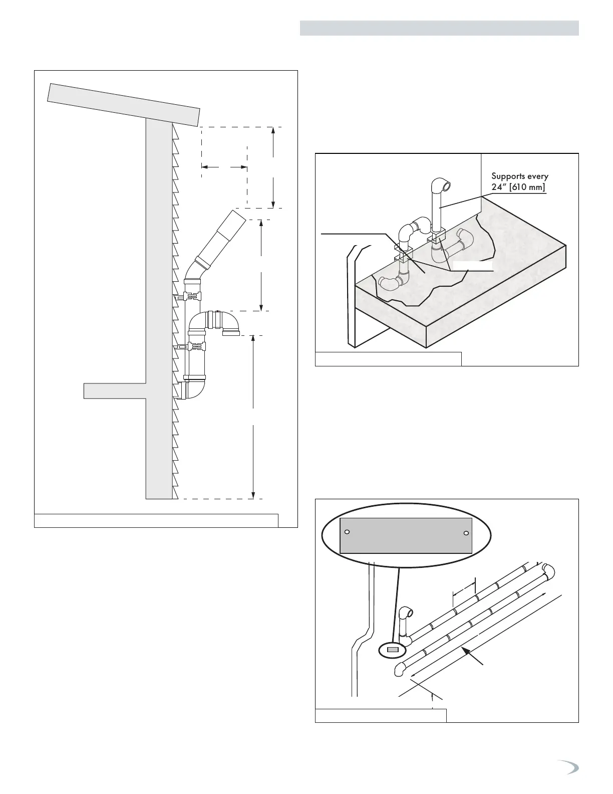
A. For every 1” of overhang, the exhaust vent must be located 1”
vertical below the overhang (12” minimum). Overhang means top
of building structure (roof) and not two adjacent walls (corner of
building).
B. Maintain minimum separation between exhaust vent and air intake
sidewall terminations, as required by local codes.
C. Maintain 12” minimum clearance above highest anticipated snow
level or grade (whichever is greater).
D. The exhaust vent must extend a minimum of 12” to a maximum of
24” beyond the building.
NOTE: These drawings are meant to demonstrate system venting only.
The installer is responsible for all equipment and detailing required by
local codes.
Intake
Exhaust
D
A
B
C
Snorkel Venting (Two Pipe Sidewall Venting Terminations
Beneath an Overhang)
Figure 43 - Two Pipe Sidewall (Horizontal Snorkel) Venting
Venting Below Grade
Supports every
24” [610 mm]
12” [305 mm]
plus snow
allowance above
grade
Air-inlet
For installations that exit the wall below grade:
1. Excavate the site to a point where the pipes are to exit as shown in
Figure 44.
2. Ensure the wall is fully sealed where the pipes penetrate.
3. The exhaust vent / air intake piping MUST be secured to the side
of the building above grade, as shown, to provide rigidity.
4. Ensure that the exhaust vent / air intake clearances are
maintained.
Outdoor Venting
[6.1 m] is permitted
for piping outside a
Vent
Gas Vent Directly Below
Keep Free of Obstructions
Vent piping outside the building is permitted under the following
conditions:
1. The maximum length outside the building is 20 feet (6.1 m). Note
that outdoor length must be included in the overall vent length
calculation.
2. All normal termination clearances are maintained.
3. The pipe is supported every 24” (610 mm).
4. The exhaust and air intake are sloped back to the boiler 1/2”
elevation for every linear foot (13 mm for every linear 305 mm).
Figure 44 - Venting Below Grade
Figure 45 - Outdoor Venting
 Loading...


