44
420012001500 - 03182024 - Rev. 04
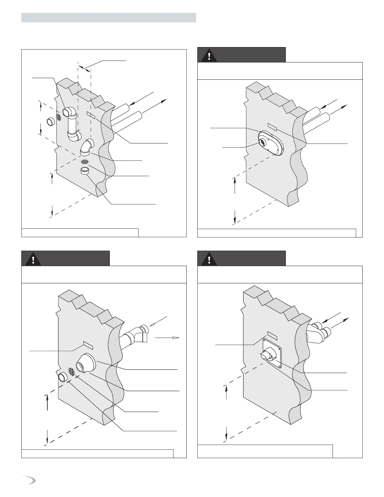
NOTE: These drawings are meant to demonstrate system venting only.
The installer is responsible for all equipment and detailing required by local codes.
Sidewall Venting Options - Direct Vent Installation
Two Pipe Termination Low Profile Termination
Concentric Termination
Vertical
Min 18”
Min. 12”
above grade
or snow level
Exhaust
4 in min
Gas Vent Directly
Below Keep Free
of Obstructions
Exhaust
Air-inlet
Air-inlet
Vent Screen
Vent pipe piece to
retain vent screen
Exhaust
Air-inlet
Min. 12”
above grade
or snow level
Vent pipe piece to
retain vent screen
Vent screen
Exhaust
through center
Air-inlet
around perimeter
(1-2” from wall)
Gas Vent Directly
Below Keep Free
of Obstructions
Air-inlet around
perimeter
Exhaust
Exhaust
Air-inlet
Gas Vent Directly
Below Keep Free
of Obstructions
Min. 12”
above grade
or snow level
Min. 12”
above grade
or snow level
Air-inlet bottom
Exhaust center
Exhaust
Air-inlet
Gas Vent Directly
Below Keep Free
of Obstructions
Refer to documentation included with termination kit for complete
installation instructions.
Refer to documentation included with termination kit for complete
installation instructions.
Refer to documentation included with termination kit for complete
installation instructions.
WARNING
WARNING
WARNING
Figure 39 - Two Pipe Sidewall Venting Detail
Figure 41 - Sidewall Concentric Termination (with Optional IPEX kit)
Figure 40 - Low Profile Sidewall Termination (with Optional IPEX Kit)
Figure 42 - Sidewall Concentric Termination
(with Optional Duravent / InnoFlue Kit)
Part 5 - Venting
 Loading...


