53
TRX Series II - Installation - Startup - Maintenance Instructions
Part 7 - Connecting Electrical Service
8. Leave the plastic connection secured to ensure the cabinet
remains sealed.
9. Insert the field power cable through the hole in the side panel;
use an appropriate strain relief/conduit hub to secure the cable to
the side panel. Fix the wiring to the green connector at the PCB;
reuse the grommet removed in step 7 to act as a strain relief at
the junction box
hole Ø 7/8"
10. Reconnect the three clips and close the Junction box.
11. Rotate and fix the control panel.
12. Reinstall the boiler front cover
13. Restore gas to the boiler.
14. Restore power to the boiler.
Figure 63 - Hole Position for Power Cord - Right Side of
Boiler
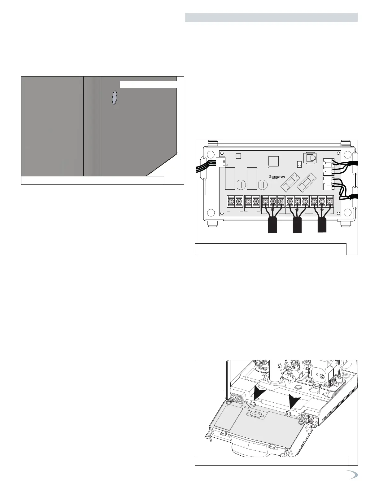
2. Connecting Power for DHW & CH Pumps (120V) and
Zone Outputs (dry contact)
3. Low Voltage Wiring Connections
To access the low voltage wiring connections:
1. Shut off the power supply at the boiler and at the circuit breaker.
2. Shut off the gas at the manual shutoff.
3. Remove the boiler front cover.
4. Rotate the control panel while pulling it forwards.
5. Disconnect the two clips See Figure 65.
6. Open the control panel cover to have access to the main PCB. See
Figure 66.
To connect power for the CH and DHW external pumps and zone
loads (pumps or valves) at the boiler junction box:
1. Shut off the power supply at the boiler and at the circuit breaker.
2. Shut off the gas at the manual shutoff.
3. Remove the boiler front cover.
4. Unlatch the bottom clips securing the junction box cover and
rotate the cover upwards unhooking the cover at the top.
5. Insert the field wiring through the hole in the side panel; use an
appropriate strain relief/conduit hub to secure the cable to the
side panel.
6. Connect the field wiring to the respective output; see Figure 64.
NOTE: CH PUMP & DHW PUMP output 120V directly.
NOTE: ZONE 1 & ZONE 2 outputs are dry contact; power must be
applied to one side. See examples in Figures 23-28.
7. Reconnect the cover of the junction box.
8. Reinstall the boiler front cover
9. Restore gas to the boiler.
10. Restore power to the boiler.
Figure 64 - 120V Connections for DHW and CH Circulators
CN3
SW1
CN10
11
CN7
CN6CN5
FUSE 5AT
FUSE 5AT
FUSE 5AT
FUSE 5AT
CN8
CN4CN9
LNL
120VAC INPUT
120VAC INPUT
DHW PUMP
NL
CH PUMP
DHW PUMP
ZONE 2ZONE 1
N
CN2
ON
1 2
to main PCB
CN22
to main
PCB
CN1
to main
PCB
CN2
Figure 65 - 120V Connections for DHW and CH Circulators