54
420012001500 - 03182024 - Rev. 04
BUS
T B 5V IN
OD TNK SYS TT1
TT2
120V
120V
120V
120V
120V
120V
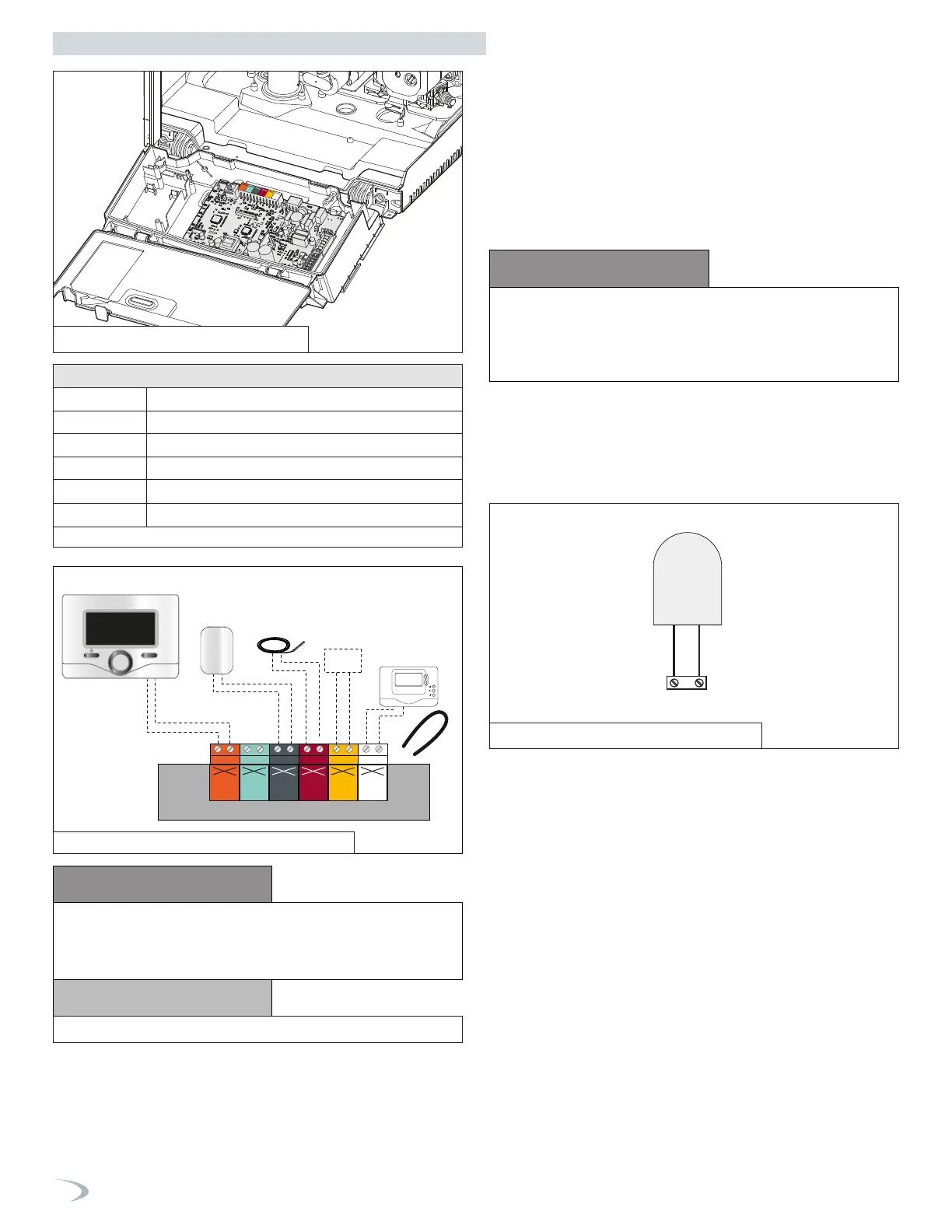
Table 19 - Low Voltage Wiring Connections
CN1
Remote Control (optional)
Outdoor
Sensor
Tank temp.
probe
System
Sensor
Room Thermostat
OK
1 2 3 4 5 6 7
BUS
T B 5V IN
OD TNK SYS TT1
TT2
120V 120V 120V120V 120V 120V
Low Voltage Wiring Connections
BUS Remote Control Connection
TT2 Room Thermostat 2
OD Outdoor Sensor
TNK Tank Temperature Sensor (Probe / Aquastat)
SYS
System Sensor (Cascade Manager boiler only)
TT1 Room Thermostat 1
CAUTION
CAUTION
DO NOT CONNECT 120V TO ANY CONTROL WIRING
CONNECTION! DOING SO WILL RESULT IN IMPROPER
OPERATION AND POSSIBLE DAMAGE TO THE BOILER. SUCH
DAMAGES ARE NOT COVERED BY PRODUCT WARRANTY!
NOTICE
REMOVE THE JUMPER FROM TT1.
4. Room Thermostat Wiring Connections
To connect a room thermostat:
1. Access the low voltage wiring connections by following the
directions in Item 3, Low Voltage Wiring Connections.
2. Loosen the cable clamp using a screwdriver and insert the wires
leading from the room thermostat.
3. Connect the room thermostat wires to the terminals indicated in
Table 19 and Figure 69.
4. Ensure that the wires are well connected and not subject to stress
when the control panel or cabinet cover are closed.
5. Outdoor Sensor Connections
Connector OD on PCB
Outdoor Sensor
NOTE: WHEN CONNECTING THE BOILER TO EXTERNAL CONTROLS,
DO NOT RUN 120V CABLES AND CABLES FOR CONTROL CIRCUITS
(WHICH ARE LOW VOLTAGE) TOGETHER. USE SEPARATE CABLES TO
PREVENT INDUCED VOLTAGE ON THE LOW VOLTAGE CIRCUITS.
6. Aquastat (Default) and Tank Sensor (Optional) Connections
(non-Combi Models)
NOTE: Some newer thermostat models may draw too much power
from the boiler and will require an additional power supply to operate
properly. Review the instructions provided with the thermostat to
determine if an additional power supply is needed. Failure to do so
could result in improper boiler and/or thermostat operation.
Figure 67 - Outdoor Sensor Connection
Figure 68 - Low Voltage Wiring Connections
Part 7 - Connecting Electrical Service
Figure 66 - Outdoor Sensor Connection
The boiler is designed for managing the production of domestic hot
water via an indirect water heater (IWH) in one of two ways:
1. AQUASTAT (default) - with DHW Mode = 2, the tank temperature
is managed through an ON/OFF aquastat installed in the tank.
2. TANK SENSOR (optional) - with the DHW Mode = 1, the boiler
manages the IWH temperature directly via an NTC sensor installed
in the tank and connected to the boiler (see electrical diagram).
The setting of the tank temperature can be adjusted by the DHW
Setpoint, accessed from the DHW Setup menu of either the User or
Tech Menu.
NOTE: When a acquastat or a tank sensor is equipped, the boiler
target temperature for DHW IWH demands can be adjusted via the
Modulation Setpoint (accessed from the Advanced Settings menu
under Tech Menu - DHW Setup) - default setting is 179
°
F.