59
TRX Series II - Installation - Startup - Maintenance Instructions
A. Gas Pipe Sizing Tables
1. Gas Pipe Sizing
This information is for reference use only. Refer to gas pipe
manufacturer specifications for actual delivery capacity. The DOE
standard for Natural Gas is 1100 BTU/ft
3
. Contact the local gas supplier
for actual BTU/ft
3
rating.
2. Natural Gas Pipe Sizing
The following tables list maximum capacity of pipe in cubic feet of
gas per hour for gas pressures of 14” or less and a pressure drop of 0.5
inches water column, based on a 0.60 specific gravity for natural gas.
Pipe Size (in.)
Length of Pipe (Feet)
BTU’s Per Hour x
1,000
Schedule 40
Metallic Pipe
(0.60 Specific Gravity,
0.5 WC Pressure
Drop)
10 20 30 40 50 60 80 100 15 0 200
3/4 360 247 199 170 151 137 117 104 83 71
1 678 466 374 320 284 257 220 195 157 134
1 1/4 1390 957 768 657 583 528 452 400 322 275
1 1/2 2090 1430 1150 985 873 791 677 600 482 412
2 4020 2760 2220 1900 1680 1520 1300 1160 928 794
3 11300 7780 6250 5350 4740 4290 3670 3260 2610 2240
4 23100 15900 12700 10900 9660 8760 7490 6640 5330 4560
3. LP (Liquid Propane) Gas Pipe Sizing
Contact gas supplier to size pipes, tanks, and 100% lockup gas
pressure regulator. Adjust propane supply regulator provided by
the gas supplier for 14 inches w.c. maximum pressure.
B. Gas Connection Requirements
1. Install the factory supplied 3/4” NPT gas adapter and gasket onto
the gas connection of the boiler.
NOTE: The boiler gas connection is a straight thread and seals via
the factory supplied gasket to the factory supplied 3/4” NPT gas
adapter. Only use Teflon tape or thread sealant on the male end of
the 3/4” NPT gas adapter, not on the boiler connection.
2. The supply line must be sized for the maximum input of the boiler
being installed. If there are additional gas appliances on the main
supply line, measure the size of the supply line according to the
COMBINED total maximum BTUH draw for the appliances as if they
were operating at the same time.
NOTE: The pipe size must not be less than ¾”.
NOTE: DO NOT USE 1/2” quick flex gas lines! Doing so will result in
improper appliance operation.
3. Measure the length of the gas supply line from the gas meter to the
boiler. The boiler must be installed downstream of the gas meter to
ensure adequate gas supply. Use the tables in this manual or refer
to the gas line manufacturer’s sizing information to determine the
correct supply pipe size.
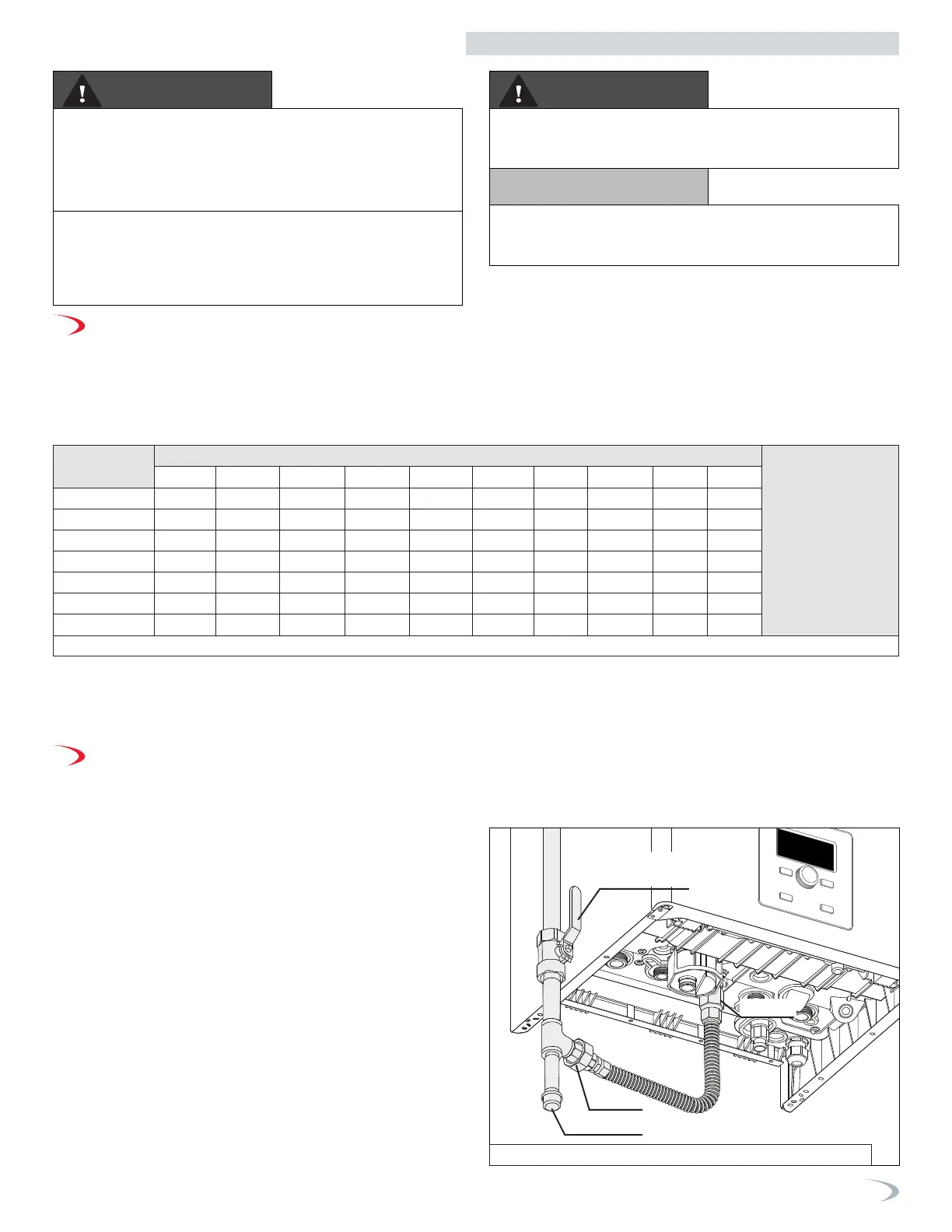
4. The National Fuel Gas Code (NFPA 54) requires that a sediment trap
(drip leg) be installed in the gas line on boilers not so equipped.
The drip leg must be accessible, a minimum of 3” in length, and not
subject to freezing conditions. See Figure 72.
5. A manual gas shut-off valve should be installed in the gas supply
line close to the boiler. See Figure 72.
6. To facilitate any future maintenance, it is also recommended
that an approved gas union fitting be installed in the supply line
between the shut-off valve and the ¾” NPT connection on the
boiler.
7. Use a manometer to test the gas pressure to make sure it meets the
minimum standards and does not exceed the maximum standards
of the boiler.
FIRE AND/OR EXPLOSION HAZARD
To avoid serious injury or death, the gas line
installation and the gas line inlet pressure test
must be done by a licensed professional.
Ensure the gas on which the boiler will operate is the same type
specified on the rating plate (natural gas or LP gas). This boiler must
be converted to propane operation. Follow Gas Conversion Manual
instructions (separate document). Failure to follow these instructions
could result in property damage, personal injury, or death.
Make sure the gas line pressures are within normal limits. Pressures
outside normal limits can result in poor performance and hazardous
operating conditions, property damage, personal injury, or death.
WARNING WARNING
Do not operate the boiler on Natural Gas or LP gas with average
sulfur rates greater than 30 mg/m3. Doing so could result in improper
product operation and failure, and WILL VOID the boiler warranty.
NOTICE
Part 8 - Gas Connections
Table 22 - Natural Gas Delivery Capacity - Refer to ANSI Z223.1 - National Fuel Gas Code, Latest Edition
Manual Gas
Shut-off Valve
Sediment trap
Union
Adapter
Figure 71 - Gas Line with Shut-Off and Sediment Trap Detail
 Loading...


