60
420012001500 - 03182024 - Rev. 04
WARNING
WARNING
NOTICE
C. Additional Precaution for Excess Flow
Valve (EFV)
If an excess flow valve (EFV) is in the gas line, check the manufacturer’s
minimum and maximum flow capacity ratings. An improperly sized
EFV will not allow for a full flow of gas to the boiler and will cause the
boiler to malfunction. See Figure 73.
D. Checking Gas Pressure at the Boiler for
Proper Operation
NOTE: Refer to Figure 74 when checking gas pressure. Loosen the
bolts before checking the gas inlet pressure.
1. The boiler and its individual shutoff valve must be disconnected
from the gas supply piping system during any pressure testing of
the system at test pressures greater than ½ psi (3.5 kPa).
2. The boiler must be isolated from the gas supply piping system by
closing its individual manual shutoff valve during any pressure
testing of the gas supply piping system at test pressures equal to or
less than ½ psi (3.5 kPa).
The minimum and maximum inlet gas line pressures must meet the
requirements shown in Table 23.
To check inlet gas pressure:
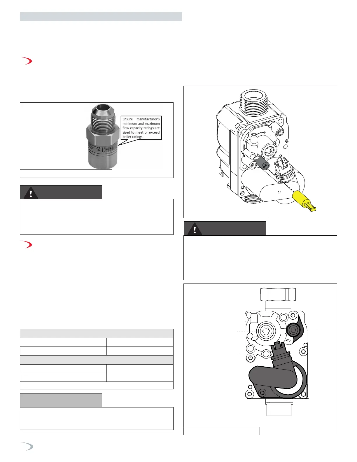
1. Remove yellow cap from line pressure test point. See Figure 74.
2. Unscrew “P in” screw.
3. Connect the manometer to the test point.
4. Check the inlet gas pressure.
5. Disconnect the manometer from the test point.
6. Tighten the “P in” screw (1 N/m).
7. Check for and repair any gas leaks.
8. Replace the yellow cap.
Natural Gas
Minimum Pressure 3.5” WC
Maximum Pressure 10.5”WC
LP Gas
Minimum Pressure 8” WC
Maximum Pressure 13”WC
4
2
1
IN
Gas Inlet
1. Line pressure Test point
2. OFFSET Adjustment Screw
4. Throttle Adjustment Screw
Figure 72 - Excess Flow Valve (EFV)
Figure 73 - Remove Yellow Cap
Figure 74 - Gas Valve Detail
When performing a pressure test on the gas line pipng, be sure the
boiler is disconnected or isolated if the test pressure is expected to
exceed 1/2 PSI (14” WC), as damage to the gas valve could occur.
Such damage could result in fire, property damage, serious personal
injury, or death.
DO NOT REMOVE OR ATTEMPT TO MAKE AN
ADJUSTMENT TO SCREWS 2 and 4 WITHOUT A
CALIBRATED COMBUSTION ANALYZER. DOING SO
COULD RESULT IN FIRE, PROPERTY DAMAGE, SERIOUS
PERSONAL INJURY, OR DEATH.
Do not fire (operate) the boiler until all connections have been
completed and the heat exchanger is filled with water. Doing so will
damage the boiler and void the warranty.
8. Leak test the gas line pipe before placing the boiler in operation.
Only use approved leak detector liquid solutions to check for leaks.
9. Do not operate the boiler until all connections have been
completed and the heat exchanger is filled with water.
Part 8 - Gas Connections
Table 23 - Gas Pressure Requirements