81
TRX Series II - Installation - Startup - Maintenance Instructions
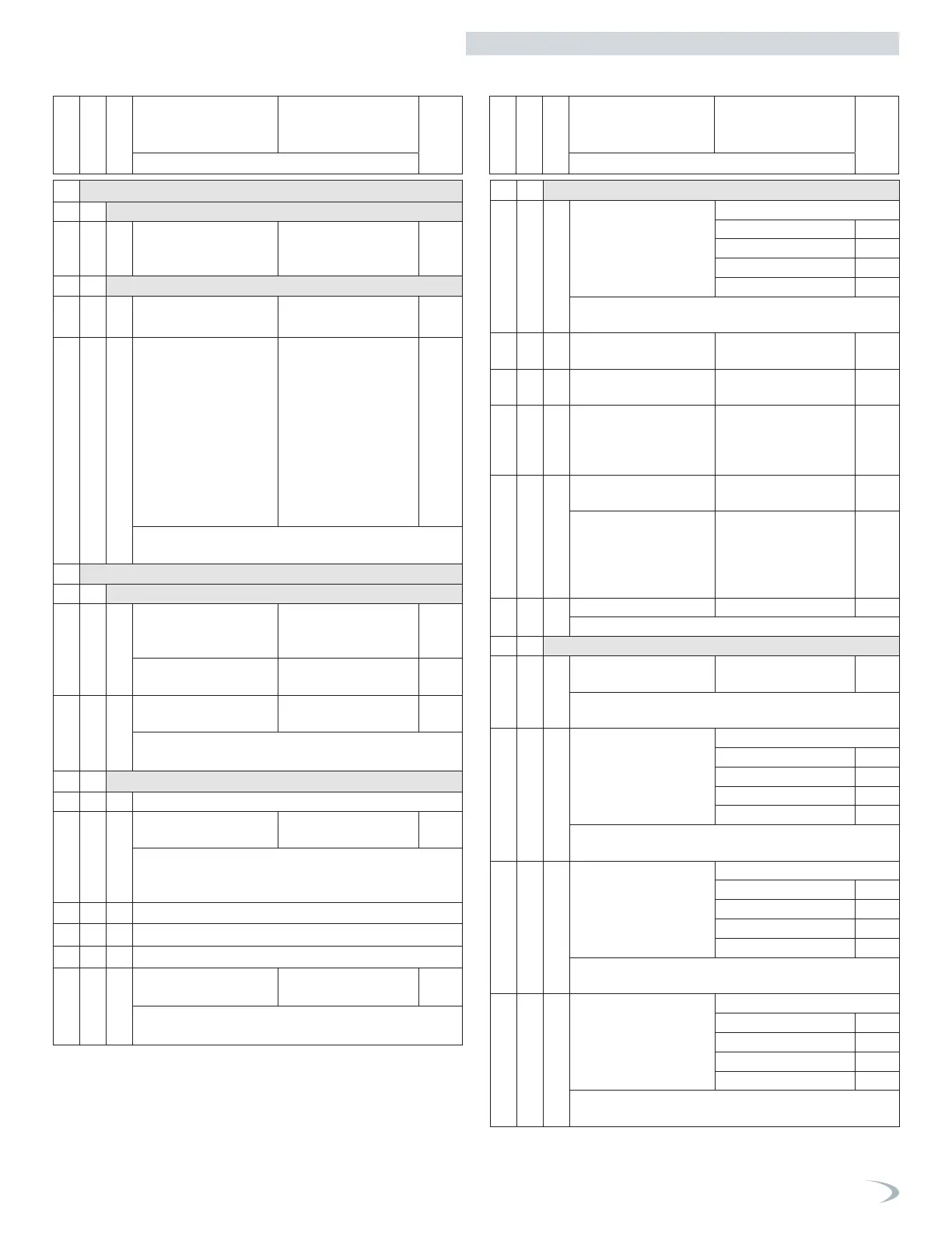
6.b Complete Menu - Parameters
0 NETWORK
0. 2 BUS NETWORK
0. 2. 0 Network presence Boiler
Remote Modem
Multifunction clip
0 4 USER INTERFACE
0. 4. 1 Backlight timing 1 - 10 minutes
or 24 hours
10
0. 4. 6 Cascade Boiler
Configuration
UNDEF = undefined
b-SIN = single boiler
b-MAS = master boiler
b-FL1 = follower #1
boiler
b-FL2 = Follower #2
b-FL3 = Follower #3
b-FL4 = Follower #4
b-FL5 = Follower #5
b-FL6 = Follower #6,
b-FL7 = Follower #7
b-SIN
RESERVED FOR CASCADE APPLICATIONS.
See Cascade Instruction Manual for details.
2 BOILER PARAMETERS
2. 0 GENERAL
2. 0. 0 DHW Setpoint
Temperature
TRX COMBI
97 - 140°F 125
Tank Setpoint (Comfort)
TRX non-COMBI
104 - 149°F 125
2. 0. 1 DHW Preheating 0 = Disabled
1 = Enabled
1
Enables/disables comfort on/off setting via COMFORT
button and parameter 2.5.0.
2. 1 FREE PARAMETERS (DO NOT USE)
2. 1. 1 DO NOT USE nnonn se vede
2. 1. 2 3-way Valve Anti-Noise
Function
0-10 0
Function can be utilized to reduce the stroke of the 3-way
valve when transitioning between the CH and DHW posi-
tions. Consult NTI Technical Support before utilizing.
2. 1. 3 DO NOT USE
2. 1. 5 DO NOT USE
2. 1. 6 DO NOT USE
2. 1. 9 Flow Sensor Type 0 = Flow Switch
1 = Flow Meter
0
TRX C models use a flowswitch.
Not applicable for non-COMBI models.
2. 2 SETTINGS
2. 2. 0 Ignition Power 25 - 65
TRX 085. 53
TRX 120. 43
TRX 110C. 40
TRX 150C. 34
RESERVED FOR TECHNICAL ASSISTANCE
Only if the PCB is replaced.
2. 2. 3 Floor or 2nd Room
Thermostat
0 = Floor
1 = Room
1
2. 2. 4 AUTO Function
(Outdoor Reset)
0 = Disabled
1 = Enabled
0
2. 2. 5 CH Start Delay
Heating ignition delay
(for new demand)
0 = ALWAYS OFF ,
1 = 10 seconds
2 = 90 seconds,
3 = 210 seconds
0
2. 2. 8 Boiler version - TRX C
CANNOT BE MODIFIED
0 = Combi 0
Boiler Version - TRX
Type of DHW control
for Indirect Hot Water
Heater (Tank Sensor or
Aquastat)
0 = NOT USED
1 = Storage with Tank
Sensor
2 = Storage with
Aquastat
2
2. 2. 9 Set boiler heating power 0 - 682 kBtu/h
Only if the PCB is changed
2. 3 BOILER CH PARAMETERS 1
2. 3. 1 Max CH Power
percentage
0 - 100 100
Limited by the absolute values defined by parameters
2.3.3 and 2.3.4, i.e., 0 = min power and 100 = max power.
2. 3. 2 Max DHW percentage
CANNOT BE MODIFIED
55 - 100
TRX 085. 56
TRX 120. 68
TRX 110C. 72
TRX 150C. 87
RESERVED FOR TECHNICAL ASSISTANCE
Only if the gas or PCB is changed.
2. 3. 3 Min percentage
CANNOT BE MODIFIED
0 - 100
TRX 085. 3
TRX 120. 2
TRX 110C. 3
TRX 150C. 2
RESERVED FOR TECHNICAL ASSISTANCE
Only if the gas or PCB is changed.
2. 3. 4 Max CH percentage
CANNOT BE MODIFIED
55 - 100
TRX 085. 56
TRX 120. 68
TRX 110C. 66
TRX 150C. 68
RESERVED FOR TECHNICAL ASSISTANCE
Only if the gas or PCB is changed.
Menu
Sub-Menu
Parameter
Description Value
Default
Setting
Note
Menu
Sub-Menu
Parameter
Description Value
Default
Setting
Note
Part 9 - Controls