83
TRX Series II - Installation - Startup - Maintenance Instructions
2. 8 RESET FACTORY SETTINGS
2. 8. 0 Reset PCB to Factory
Default Settings
Do you really want to perform
the RESET? If you pressOK
button, the reset command
will be executed otherwise, by
way of ESC, the orevious page
is shown.
To Reset all parameter settings, press the OK button.
WARNING: Always check PCB settings if restoring factory
default settings on a replacement controller. Replacement
controllers have generic settings that may not be specific
to the boiler model.
2. 9 OTHER PARAMETERS 1
2. 9. 3 Flue gas sensor type 1 = NTC 1
2. 10 OTHER PARAMETERS 2
2.
10.
0 CH On Differential
Temperature
0 - 36°F 11
Determines how much the boiler outlet temperature can
drop below target before turning the boiler back on.
2.
10.
1 DHW Modulation
Setpoint
68 - 179°F 179
Boiler target temperature duringa DHW demand.
Not applicable for Combi models.
2.
10.
2 Tank on Differential 0 - 36°F 0
Determines how much the DHW storage tank
temperature can drop below target before initiating a
DHW demand. Only applicable when 2.2.8 = 1.
2.
10.
3 Emergency Setpoint 68 - 179°F 113
Sets Follower boileroperating temperature when
communication with the Master is lost, or when the
System Sensor is disconnected.
See Cascade Instruction Manual.
2.
10.
4 DHW/CH Shifting
priority time
0 - 1440 minutes 45
Determines how long a CH or DHW demand can last
before the priority is switched. First priority is with DHW.
A value of 0 keeps the priority with DHW indefinitely.
2.
10.
5 CH switch-off offset 4 - 36°F 11
Determines how much the boiler outlet temperature can
go over target before turning the burner off.
2.
10.
6 CH/DHW anti-water-
hammer func.
0 = OFF, 1 = ON 0
2.
10.
7 Antifreeze Disable
Function
0 = Disabled
1 = Enabled
0
To disable antifreeze function, set 2.10.7 = 1
2.
10.
8 CH forced diverter
position
0 = OFF, 1 = ON
2. 13 BOILER SETTINGS 2
2.
13.
0 Flue temperature where
power is limited
130 - 199°F 190
2.
13.
1 Flue temperature limit 130 - 199°F 199
4 ZONE 1 PARAMETERS
4. 0 TEMPERATURE SETTINGS
4. 0. 0 Room Setpoint
(Comfort)
50 - 86 °F 66
Only applicable when using an NTI room sensor
4. 0. 1 Room Setpoint
(Reduced)
32 - 86 °F 61
Only applicable when using an NTI room sensor
4. 0. 2 Zone 1 Fixed Water
Temp
68 - 179 °F 179
4. 0. 3 Room Setpoint
(Holiday/Anti-frost)
35 - 75 °F 41
Only applicable when using an NTI room sensor.
Changes all zones
4. 0. 5 CH Target temperature
logic
0 = Max active
zone target
1= Z1,Z2,Z3....etc.
2= Min active
zone taget
1
4. 1 AUTOMATIC WINTER MODE
4. 1. 0 Warm weather
shutdown
0 = OFF
1 = ON
0
4. 1. 1 WWSD threshold 50 - 86 °F 68
4. 1. 2 WWSD Switchoff delay 0 - 300 minutes 2
4. 2 ZONE 1 SETTINGS
4. 2. 1 AUTO Temperature
Control Mode
0 = Fixed Outlet
1 =Basic On/Off
2 =Room Temp
3 =Outdoor Temp
4 =Room&Outdoor
3
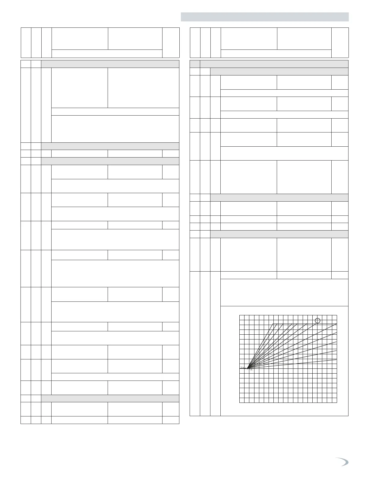
4. 2. 2 Heating Curve Slope 0.2 - 3.5 1.3
The greater the slope, the quicker the target temperature
rises as the outdoor temperature decreases. Applicable
when 4.2.1 = 3 or 4.
See J. Slope of Outdoor Reset Curve.
Outlet temperature
Outdoor temperature
Setpoint of the
room temperature
°F
73
70
66
86
95
77
50
32
104
122
140
158
176
194
°F
4150596877
3.5
3.0
2.5
2.0
1.8
1.5
1.3
0.8
1.0
0.6
0.4
0.2
32 23 14 5 -4 -13 °F
Menu
Sub-Menu
Parameter
Description Value
Default
Setting
Note
Menu
Sub-Menu
Parameter
Description Value
Default
Setting
Note
Part 9 - Controls
 Loading...


