C - 8 en-938821/2
C.1.2 Cables
!
CAUTION
For correct interference suppression, the cable shieldings must be earthed in accordance
with the instructions of Sec. C.1.1.1.
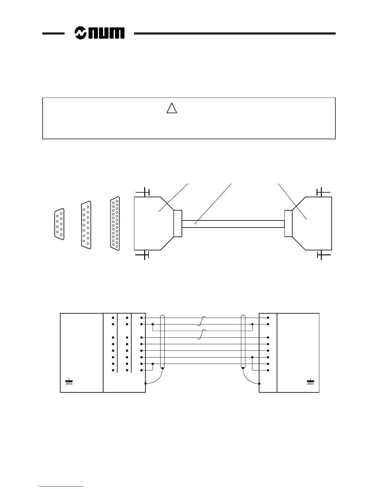
C.1.2.1 RS 232/Peripheral Device Serial Connecting Cable
The connecting cable must be adapted to the peripheral device by not wiring the signals that are not going to be used
and by using an appropriate Sub.D connector (See peripheral manual).
1
13
25 contacts
25
Solder side
12 3
14
5
1
6
9
9 contacts
8
1
9
15
15 contacts
1 - 9-, 15- or 32-contact male Sub.D connector on NUM side
2 - Shielded cable depending on the peripheral (2 twisted pairs and 4 conductors for complete connection, 0.2 mm
2
minimum cross sectional area)
3 - Plug depending on the peripheral
CONNECTOR
BODY
PROTECTIVE
EARTH
PROTECTIVE
EARTH
CONNECTOR
BODY
TD
RD
RTS
CTS
DTR
7
2
3
4
5
20
6
8
GND
DSR
DCD
RD
TD
CTS
RTS
DSR
DTR
DCD
GND
5
3
2
7
8
4
∗
6
∗
1
∗
7
1
3
12
5
14
6
13
SUB.D
9 cont. 15 cont. 25 cont.
∗ Contacts 1, 4 and 6 must not be connected on the 9-contact connector of the V2 machine processor and V2 CNC.
Without control signals, interconnect:
- CTS and RTS
- DSR, DCD and DTR
on the NUM side.
With only RTS and CTS control signals, interconnect DRS, DCD and DTR on the NUM side.