18 | 4307 & 4310 Blower
4-Way Plug Adjustment Procedure:
Use at inial installaon or for adjustment use steps 6 to 10.
1. Remove all hardware from center thread
2. Install Brass washers and place handle into proper t posion based on your
installaon direcon.
3. Install cup washer and adjusng nut and secure to at least nger ght.
4. Turn the adjusng nut a half to ¾ turn to pull the plug o seat posion
5. Test valve movement: Valve should move freely
6. If valve does not move freely, review for other obstrucons or ghten adjusng
nut by ¼ turn unl free movement occurs.
7. Once free movement is established install jam nut unl nger ght
8. Use two wrenches and ghten jam nut while holding adjustment nut steady
9. Test valve movement: Valve should move freely
10. Valve is now adjusted and ready for installaon.
Note: Use narrow wrench to hold adjusng nut while ghtening jam nut.
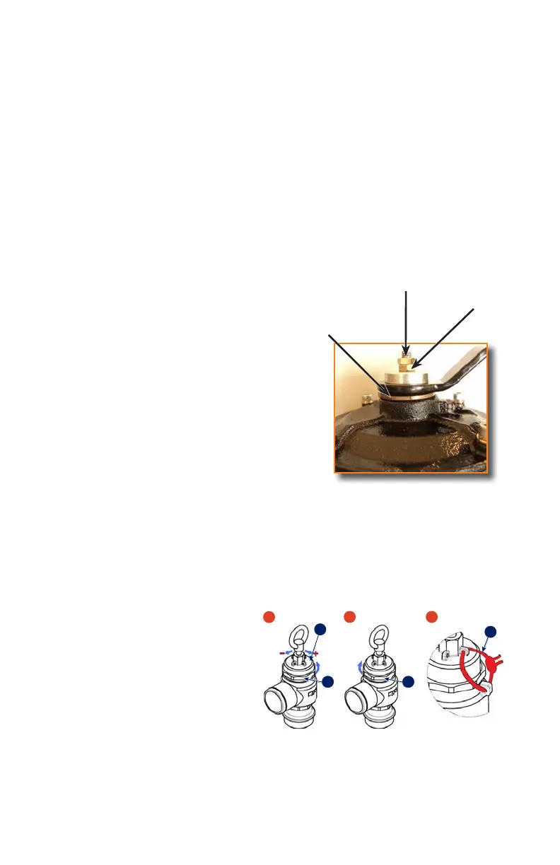
Dry Lubed Bronze
Thrust Washer
Adjusting Nut
Jam Nut
Four Way Valve cont.
Pressure Relief Valve
If the blower is intended to be used in pressure mode then a pressure relief valve
is required. NVE recommends the use of Kunkle pressure relief valves as they have
been proven to work well and have sucient ow capacity.
Picture 1. 1. Unscrew the lock nut “A”
2. Turn the spring-tightener “B”
Picture 2. Once obtained the desired pressure, screw down the lock nut “A”
Picture 3. Fix the setting, using the rings “C” Situated on the body and on the spring
tightener
Pressure Relief Valve
Setting Instructions
Pressure Relief Valve
V
ia delle Acacie 8 - Z.I. D4 - P.O. Box 64 - 28075 GRIGNASCO (N0) ITALY
Export dept. +39 - 0163 - 415 221 / 222 Fax. +39
- 0163 - 411 914
Web www.riv-vg.com www.velattagroup.com E-mail expor t.sa l e s @ r i v-vg.com
PRESSURE RELIEF VALVES - SETTING INSTRUCTION
P
icture 1
1) Unscrew the lock nut "A”
2) Turn the spring-tightener “B”,
Clockwise to increase the pressure.
Anti-clockwise to reduce the pressure
Picture 2
Once obtained the desired pressure, screw
down the lock nut “A”
Picture 3
Fix the setting, using the rings “C”
Situated on the body and on the spring-
tightener
B
1
2
3
A A
C
nvesalesrep.com | 888.814.9191