nVent.com | 67
APPENDIX C—WIRING DIAGRAMS
The following drawings provide sample wiring diagrams for the 910 Series control products
and optional accessories. Please contact your local nVent representative for information
regarding other available options.
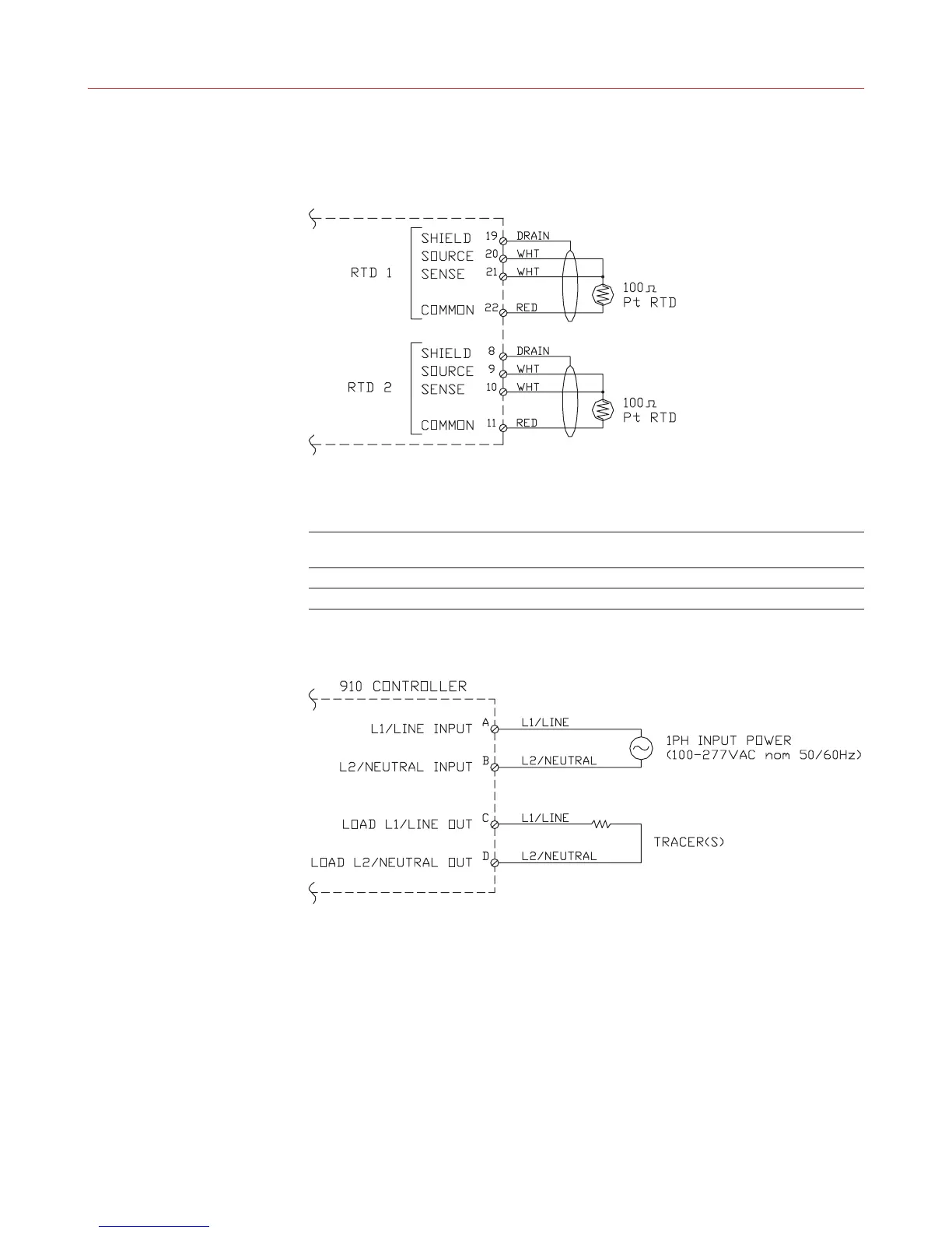
C.1 TS WIRING
Note: Temperature sensor manufacturers may use different lead wire colors than those shown
in the diagram above. Some common color combinations are shown in the table below, but
others may also be available. See Sections 2.7.1 and 8.2.1 for additional details.
Lead Wire Lead Wire Lead Wire
Signal Description Color Scheme #1 Color Scheme #2 Color Scheme #3 (IEC 751)
Source White White Red
Sense White Black Red
Common Red Red White
C.2 POWER WIRING