Hardware setup
BLDC Control Demo User's Guide, Rev. 6, 06/2020
NXP Semiconductors 5
4.3.1.
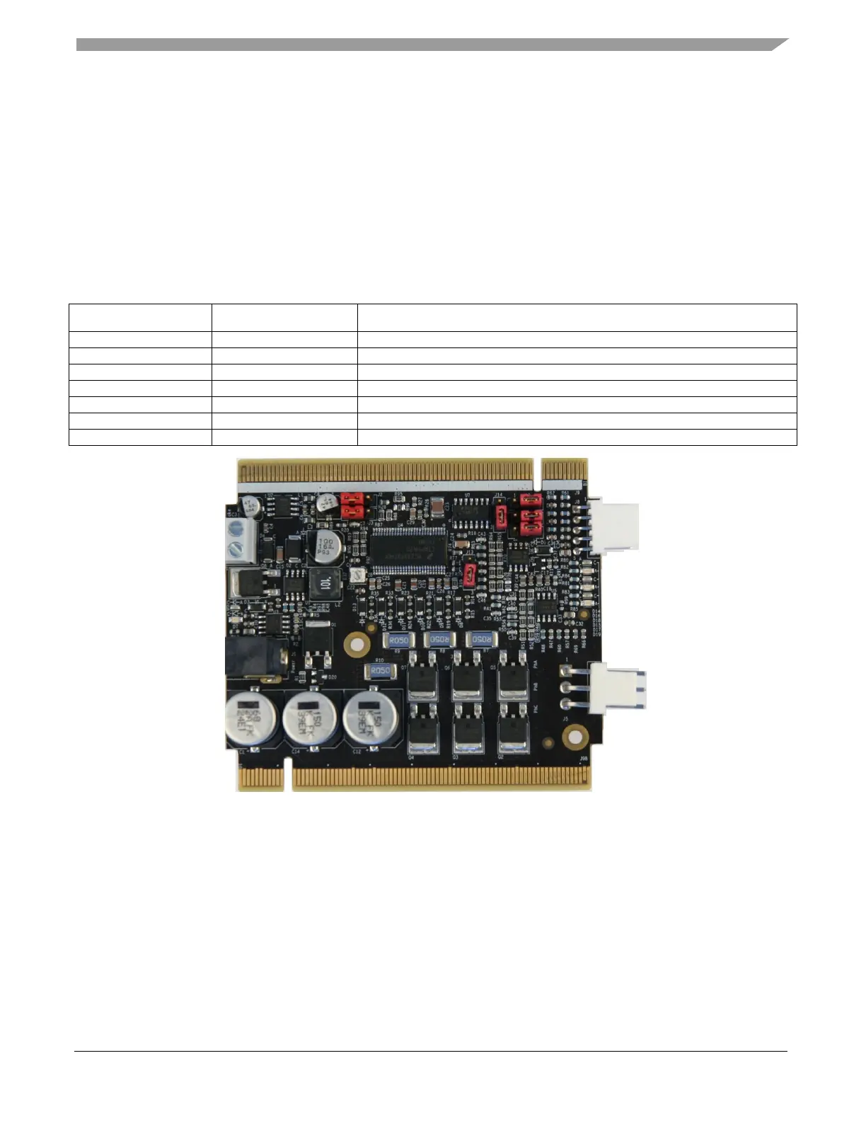
TWR-MC-LV3PH module
The 3-Phase Low-Voltage Motor Control module (TWR-MC-LV3PH) is a peripheral Tower System
module, interchangeable across the Tower System. The phase voltage and current feedback signals are
provided. These signals enable a variety of algorithms to control the 3-phase PMSM and BLDC motors.
A high level of board protection (over-current, under-voltage, over-temperature) is provided by the
MC33937 pre-driver. Before you insert the TWR-MC-LV3PH module into the Tower System, ensure
that the jumpers on your TWR-MC-LV3PH module are configured as follows:
Table 4. TWR-MC-LV3PH jumper settings
Jumper Setting Function
Selects the internal analog power supply.
Selects the internal analog power reference (GND).
Selects V_SENSE_DCB_HALF.
Figure 3. TWR-LV-MC3PH jumper settings