UM11158 All information provided in this document is subject to legal disclaimers. © NXP B.V. 2022. All rights reserved.
User manual Rev. 1.6 — 17 March 2022 8 of 24
NXP Semiconductors
UM11158
LPCXpresso55S69/55S28 Development Boards
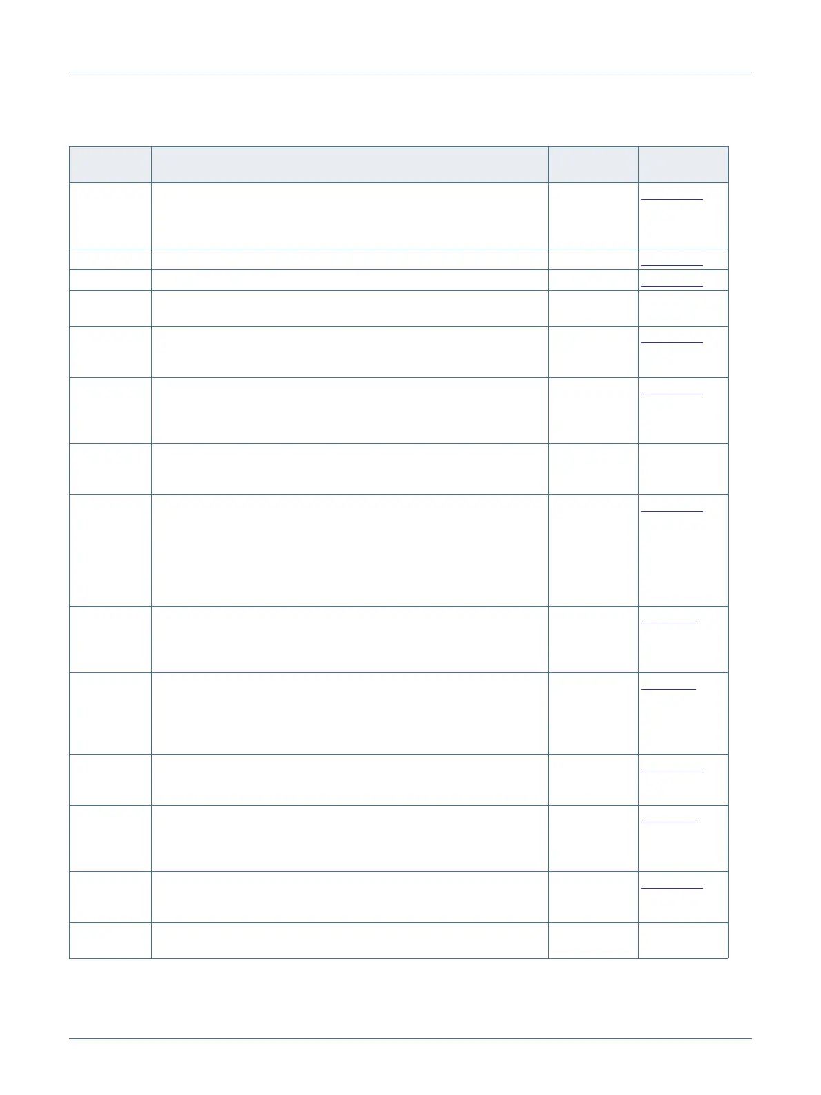
P8 Serial port header
0.1” header providing convenient access to Flexcom 0 USART (the
USART used for ISP boot). When using this port install jumper P1 to
disable the Link2 connection to this port.
n/a
Section 6.2
P9 LPC55Sxx USB1 (high speed) micro AB port connector n/a Section 6.1
P10 LPC55Sxx USB0 (full speed) micro AB port connector n/a Section 6.1
P11, P26,
P27
Headers for external core voltage supplies (not installed). Do not use
these headers unless instructed to do so by NXP.
n/a n/a
P12 This header can be used to measure the voltage drop across a 2.43
ohm resistor connected in line with the LPC55Sxx VDD supply, and
hence measure current consumption.
Not installed
Section 5.2
P13 Current measurement header for LPC55Sxx. This header is in line with
the VDD supply of the LPC55Sxx, with a zero ohm resistor (R92)
installed in parallel with it. To measure supply current to the LPC55Sxx,
remove R92 and insert an ammeter between the pins of P13.
Not installed
Section 5.2
P14 Host header for LPC55Sxx reset control.
This header is provided for convenient connection of a reset control
input to the LPC55Sxx from an off-board host.
Not installed See schematic
P15 ADC reference connector
This header provides an access point to inject positive and negative
voltage references for the LPC55Sxx ADC.
An external positive reference may be connected to pin 1. Note that a
solder jumper / zero ohm resistor must be in position 2-3 on J8.
An external negative reference may be connected to pin 3. Note that a
solder jumper / zero ohm resistor must be in position 2-3 on J9.
VREFP=VDD
VREFN=GND
Section 9.1
P16-P19 LPCXpresso expansion connectors, including Arduino R3 compatible
site. Provides connectivity to SPI (high speed SPI), USART (Flexcom
2), I2C (Flexcom 4 and Flexcom 1), I2S (Flexcom 7), ADC0, GPIO and
PLU pins.
n/a
Section 8.
P20 PMod expansion connector / Host interface connector
This connector provides access to the SPI (Flexcom 3) and I2C
(Flexcom 1) ports that support LPC55Sxx ISP mode, along with 2 GPIO
lines. When using the SPI port at this connector ensure jumper P1 is
installed to disable the connection to the Link2 debug probe.
Not installed
Section 8.
P21 SD card slot
8-bit, full size card slot connected to the LPC55Sxx SD0 interface.
Supports 3.3V operation only.
n/a Section 7.2
P23, P24 Mikroe Click site
Provides connectivity to standard Mikroe Click connectors. Shares SPI,
ADC, I2C and USART connections with the P16-P19 expansion
connectors.
n/a
Section 8.
P25 A header may be added at P25 to provide a convenient way to
enable/disable the on-board accelerometer. If this header is used,
remove the zero ohm resistor R20, which is in parallel with this header.
Not installed Section 7.3
P28 ADC0 differential input connector. This header provides access to the
ADC0 negative and positive inputs, plus a ground pin.
n/a See schematic
Table 1. Indicators, buttons, connectors and LEDs
Circuit
reference
Description Default Reference

 Loading...


