Do you have a question about the NXP Semiconductors MPC5777C and is the answer not in the manual?
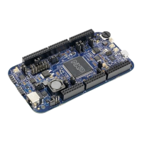
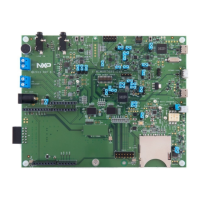
Details the modular design of the MPC5777C EVB, using daughter cards for MCU flexibility.
Lists compatible daughter cards for the MPC5777C motherboard and their specifications.
Explains the 12V DC power input and onboard regulators for EVB and MCU operation.
Details the setup for two high-speed CAN transceivers and DB9 connectors on the EVB.
Describes the DB9 connector and RS232 transceiver for PC or terminal connection.
Explains the LIN transceiver and connectors (Molex and 0.1in header) for LIN communication.
Details the RJ45 Ethernet connector and transceiver, and their jumper settings.
Describes the prototyping area with plated pads for custom circuitry and power access.
Lists and describes available test points for signals and references on the motherboard.
Details MCU power connections to the motherboard and options for onboard regulators.
Explains terminal power input for daughter card use without the motherboard.
Describes using the onboard Power System Basis Chip (SBC) for standalone operation.
Details the reset switch, LEDs, and jumpers for reset functionality.
Shows the circuit for the 40 MHz crystal oscillator for MCU clocking.
Describes the 14-pin JTAG debug connector and its jumper settings.
Provides pinout information for the 50-pin SAMTEC connector for emulation.
Details the USB Type B connector and FT232RQ chip for USB to serial UART.
Explains the connection of MCU Fast Ethernet Controller signals to the motherboard.
Describes the high-speed serial bus for inter-device communication.
Lists MCU interfaces accessible on the motherboard via headers.
Lists test points for signals and connections on the 416 daughter card.
Guides on using daughter cards standalone with external power or PowerSBC.
Details MCU power connections and jumper options for various supply modes.
Explains terminal power input for standalone daughter card operation.
Describes using the onboard Power System Basis Chip (SBC) for standalone use.
Details the reset switch, LEDs, and jumpers for reset functionality.
Shows the circuit for the 40 MHz crystal oscillator for MCU clocking.
Describes the 14-pin JTAG debug connector and its jumper settings.
Provides pinout information for the 50-pin SAMTEC connector for emulation.
Details the USB Type B connector and FT232RQ chip for USB to serial UART.
Explains the connection of MCU Fast Ethernet Controller signals to the motherboard.
Describes the EBI available on 516 BGA, interfaced with SRAM.
Describes the high-speed serial bus for inter-device communication.
Lists MCU interfaces accessible on the motherboard via headers.
Lists test points for signals and connections on the 516 daughter card.
Guides on using daughter cards standalone with external power or PowerSBC.
Details the default jumper configuration of the EVB motherboard as delivered.
| Brand | NXP Semiconductors |
|---|---|
| Model | MPC5777C |
| Category | Motherboard |
| Language | English |