Do you have a question about the NXP Semiconductors LPCXpresso54608 and is the answer not in the manual?
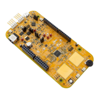
Quick reference to main board components, configurable items, visual indicators, and expansion connectors.
Instructions for loading applications via USB mass storage boot mode for LPCXpresso546x8 boards.
Guide to initiating debug sessions using the integrated Link2 Debug Probe with MCUXpresso IDE and other tools.
Steps to install and configure the MCUXpresso IDE for debugging the LPCXpresso boards.
Steps to install and configure third-party tools like Keil and IAR for debugging the LPCXpresso boards.
Guidance on connecting and using an external debug probe with the LPCXpresso boards for debugging.
Explanation of the LED indicator on the Link2 debug probe for boot status.
Procedure for programming or updating the firmware of the on-board Link2 Debug Probe.
Details on the Virtual COM port functionality provided by the Link2 Debug Probe for serial communication.
How to configure the LPCXpresso board to act as a debug probe for an external target MCU.
Overview of methods for measuring current on the LPCXpresso546x8/540xx/54S0xx board.
Measuring current by using Vsense resistors and a voltmeter.
Measuring VDD current by inserting an ammeter into the circuit.
Utilizing the board's on-board current measurement circuit for VDD current monitoring.
Information on using the on-board current measurement circuitry with expansion boards.
Details on USART ports and VCOM support provided by the LPCXpresso boards.
Overview of the full-speed and high-speed USB ports on the LPCXpresso boards.
Description of the Host Expansion Header (J14) for connecting external devices.
Description of the PMod Slave Expansion Header for connecting PMod peripherals.
Details on expansion connectors, including Arduino Uno compatibility.
Information on the on-board 10/100 Mbps Ethernet MAC and PHY.
Details on the Smart Card interface available on specific revisions of the board.
Information on the on-board SDRAM used by the LPCXpresso boards.
Information on the on-board Quad SPI flash memory.
Details on the LCD display panel with capacitive touch controller.
Information about the on-board audio codec and its interfaces.
Description of the full-size SD card slot and its interface.
Information on the NXP MMA8652FCR1 accelerometer on the board.
Details on the incorporated low-power Knowles digital microphone.
Description of the USER button and its function for generating interrupts.
Overview of the layout and jumpers on the CAN-FD Shield board.
Description of jumper settings for the CAN-FD Shield.
Instructions for installing the CAN-FD Shield board onto the LPCXpresso board.
Explanation of the pre-installed demo code for the CAN-FD Shield.
Information on obtaining and using other example code for the CAN-FD Shield.
Legal disclaimers regarding warranty, liability, and suitability of products.
List of trademarks associated with the products.
| Brand | NXP Semiconductors |
|---|---|
| Model | LPCXpresso54608 |
| Category | Motherboard |
| Language | English |