LPCXpresso boards for LPC546xx/LPC540xx/LPC54S0xx families of
MCUs
All information provided in this document is subject to legal disclaimers.
© NXP B.V. 2017-2019. All rights reserved.
Rev. 2.1 — 7th January 2019
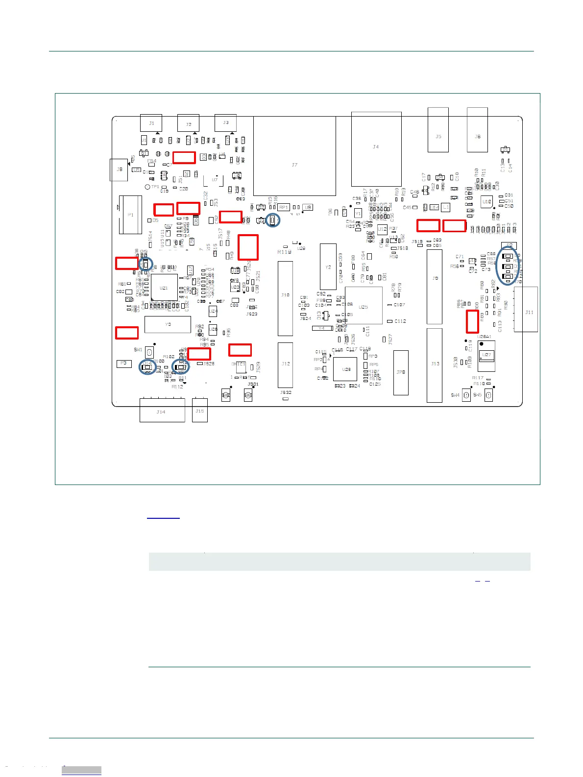
Fig 3. Jumper and LED locations
Table 1 lists the function of each jumper.
Table 1. Jumpers
Target processor selection for the on-board Debug Probe.
Jumper open (default) the LPC546x8/540xx/54S0xx Target SWD
interface enabled. Normal operating mode where the Target SWD
is connected to either the on-board Link2 Debug Probe or an
external Debug Probe.
Jumper shunted, the LPC546x8/540xx/54S0xx Target SWD
interface is disabled. Use this setting only when the on-board
Link2 Debug Probe is used to debug an off-board target MCU.
Debug probe
DFU boot
JP1
JP2
JP5
JP6
JP9
JP7
JP3
JP10
JP11
JP12
JP13
JP4
Reset LED
Power LED
SD/MMC card
Power LED
Link2 boot LED
Downloaded from Arrow.com.Downloaded from Arrow.com.Downloaded from Arrow.com.Downloaded from Arrow.com.Downloaded from Arrow.com.Downloaded from Arrow.com.Downloaded from Arrow.com.

 Loading...


