Do you have a question about the NXP Semiconductors arm LPCXpresso55S36 and is the answer not in the manual?
List of keywords associated with the document for search and indexing purposes.
A brief summary of the document's content and scope.
Defines acronyms and abbreviations used throughout the document.
Lists and explains additional documents and resources for further information.
Details the items included in the LPCXpresso55S36 board kit.
Illustrates the overall block diagram of the LPCXpresso55S36 board.
Describes the key features of the LPCXpresso55S36 board.
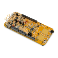
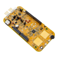
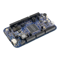
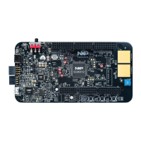
Provides visual representations of the LPCXpresso55S36 board.
Details the various connectors available on the LPCXpresso55S36 board.
Explains the function and configuration of jumpers on the board.
Describes the push buttons and status LEDs on the LPCXpresso55S36 board.
Details the primary and secondary power supply sources for the board.
Describes the available clock generators and their frequencies.
Explains the functionality and connectors of the USB interface.
Details the USART module access and connection diagrams.
Describes the I2C module access and bus device map.
Explains the I2S interface and bus device map.
Details the high-speed SPI interface and its connections.
Describes the controller area network (CAN) interface.
Explains the improved inter-integrated circuit (I3C) interface.
Details the onboard octal flash memory and external flash connector.
Describes the digital microphone interface and connectors.
Explains the mikroBUS socket for hardware expandability.
Describes the motor control and Arduino socket interfaces.
Lists target MCU pins used as GPIOs and interrupt sources.
Lists known board errata and their workarounds.
Introduction to the MCU-Link debug probe architecture and its features.
Guide for installing drivers and updating the MCU-Link firmware.
Summarizes the mandatory and optional features of MCU-Link.
Describes different debug scenarios using MCU-Link or external debuggers.
How to connect the target MCU via USB-to-UART bridge using MCU-Link.
Connecting the target MCU via USB-to-SPI or USB-to-I2C bridges.
Using MCU-Link as a USB-to-GPIO bridge for target MCU control.
Details on measuring voltage, current, and power consumption.
Explanation of the status LEDs for MCU-Link modes.
Defines key terms used in the document.
Provides warranty, liability, and suitability for use disclaimers.
Lists referenced brands, product names, and trademarks.
| Brand | NXP Semiconductors |
|---|---|
| Model | arm LPCXpresso55S36 |
| Category | Motherboard |
| Language | English |