MPC5777C EVB User Guide, Rev. 1
6 NXP Semiconductors
NOTE
Not all the supported daughter card MCUs require all the supplies to be
switched on. Please refer to Section 4 “Configuration — MPC5777C-
416DS Daughter card” for details.
3.1.3 Power Switch, Status LEDs and Fuse
The main power switch (slide switch SW5) can be used to isolate the power supply input from the EVB
Voltage regulators if required.
• Moving the slide switch to the right (away from connector P33) will turn the EVB on
• Moving the slide switch to the left (towards connector P33) will turn the EVB off
When power is applied to the EVB, four green power LEDs adjacent to the voltage regulators show
the presence of the supply voltages as follows:
• LED D9 – Indicates that the 5.0 V linear regulator is enabled and working correctly
• LED D11 – Indicates that the 5.0 V switching regulator is enabled and working correctly
• LED D12 – Indicates that the 3.3 V switching regulator is enabled and working correctly
• LED D13 – Indicates that the 1.25 V switching regulator is enabled and working correctly
If no LED is illuminated when power is applied to the EVB and the regulators are correctly enabled
using the appropriate jumpers, it is possible that either power switch SW5 is in the “OFF” position or
that the fuse F1 has blown. The fuse will blow if power is applied to the EVB in reverse-bias, where a
protection diode ensures that the main fuse blows rather than causing damage to the EVB circuitry. If
the fuse has blown, check the bias of your power supply connection then replace fuse F1 with a 20mm
1.5A fast blow fuse.
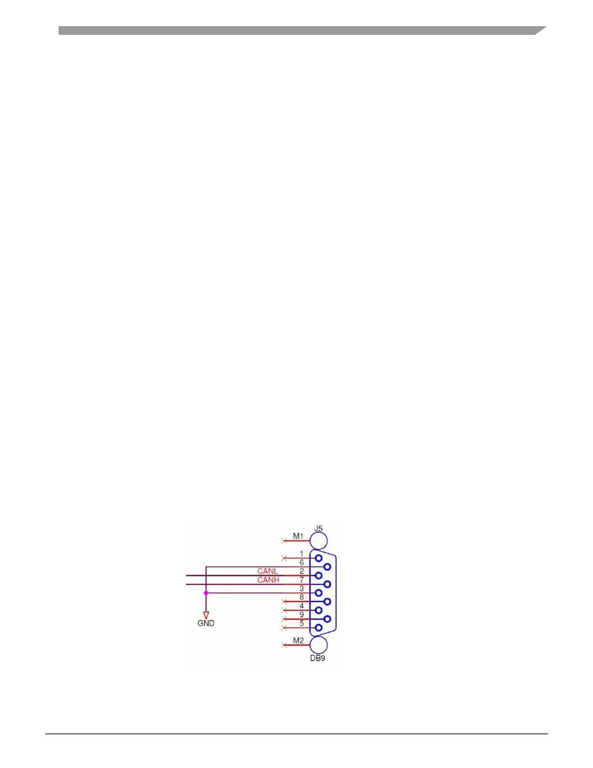
3.2 CAN Configuration
The EVB has two NXP TJA1041T high speed CAN transceivers and two standard DB9 connectors
to provide physical CAN interfaces for the MCU.
The pinout of the DB9 connectors (J5/J6) is shown in Figure 5.
Figure 5: CAN DB9 connector Pin out