MPC5777C EVB User Guide, Rev. 1
7 NXP Semiconductors
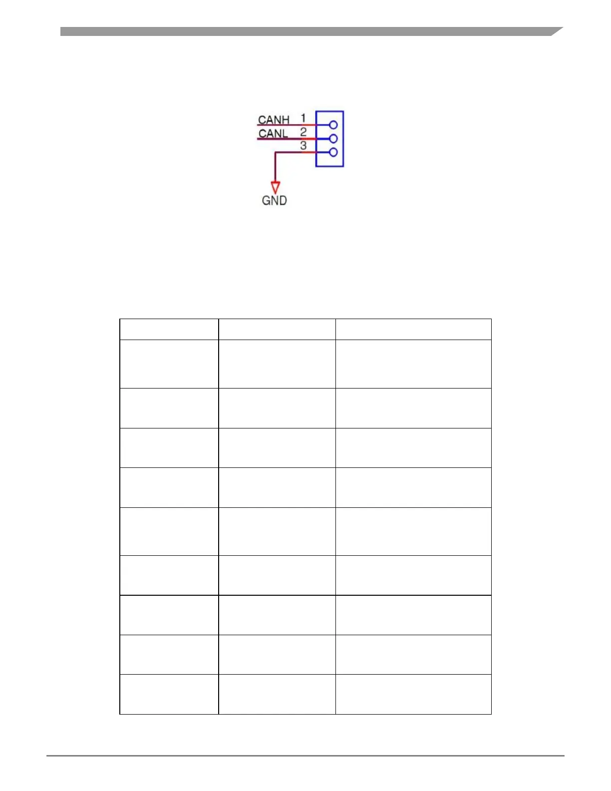
For flexibility, the CAN transceiver I/Os are also connected to two standard 0.1 in. connectors (P4 and P5)
at the top side of the PCB. The pin-out for these connectors is shown in Figure 6.
Figure 6: CAN 3pin header interface connector
By default the CAN interfaces are not enabled. To enable the CAN interfaces the jumpers detailed in
Table 2
need to be placed,
Table 2:
CAN control jumpers
 Loading...