15
TABLE 2
MODEL VOLTS/PHASE/HZ
COMPRESSOR
MCA MFS
RLA LRA MCC FLA
C270WM
208-230/3/60 18.60 100.00 29.00 28 45
440-480/3/60 10.90 77.00 17.00 17 25
400/3/50 5.40 39.00 8.50 9 12
C540WM 208-230/1/60 27.90 175.00 43.50 42 60
C60A 208-230/3/60 19.90 115.00 31.00 29 45
C60A 460/3/60 8.70 63.00 13.50 13 20
C90 208-230/3/60 24.00 196.00 37.50 35 50
C90 460/3/60 11.50 100.00 18.00 17 25
C125 208-230/3/60 28.20 225.00 44.00 40 60
C125 460/3/60 14.10 114.00 22.00 20 30
C185 208-230/3/60 35.30 239.00 55.00 49 80
C185 460/3/60 17.90 125.00 28.00 25 40
C250 208-230/3/60 48.10 300.00 75.00 68 110
C250 460/3/60 21.80 150.00 34.00 31 50
Abbreviations:
RLA = Running Load Amps; LRA = Locked Rotor Amps;
FLA = Full Load Amps; MCA = Minimum Circuit Ampacity;
MCC = Maximum Continuous Current;
MFS = Maximum Fuse Size
13
Figure 3
ELECTRICAL REQUIREMENTS
CORRECT POWER SUPPLY!
Ensure the power supply at the job site matches the
voltage and phase listed on the HPWH rating label
before connecting power to the HPWH unit.
•
Damage caused to the HPWH as the result of applying
the wrong voltage or phase is not covered under the
limited warranty.
•
Energizing the HPWH with the wrong voltage or phase
will cause permanent damage to the HPWH unit.
•
CAUTION
Ensure the power supply voltage and phase at the job site
matches the power supply ratings listed on the HPWH data
sticker label BEFORE INSTALLATION BEGINS.
The installation must conform with these instructions and the
local code authority having jurisdiction and the requirements
of the power company. In the absence of local codes, the
installation must comply with the current editions of the National
Electrical Code, ANSI/NFPA 70 or the Canadian Electrical Code
CSA C22.1.
Voltage applied to the HPWH should not vary more than +5% to
-10% of the voltage requirement listed on the HPWH rating label
for satisfactory operation.
VOLTAGE & AMPERAGE RATINGS
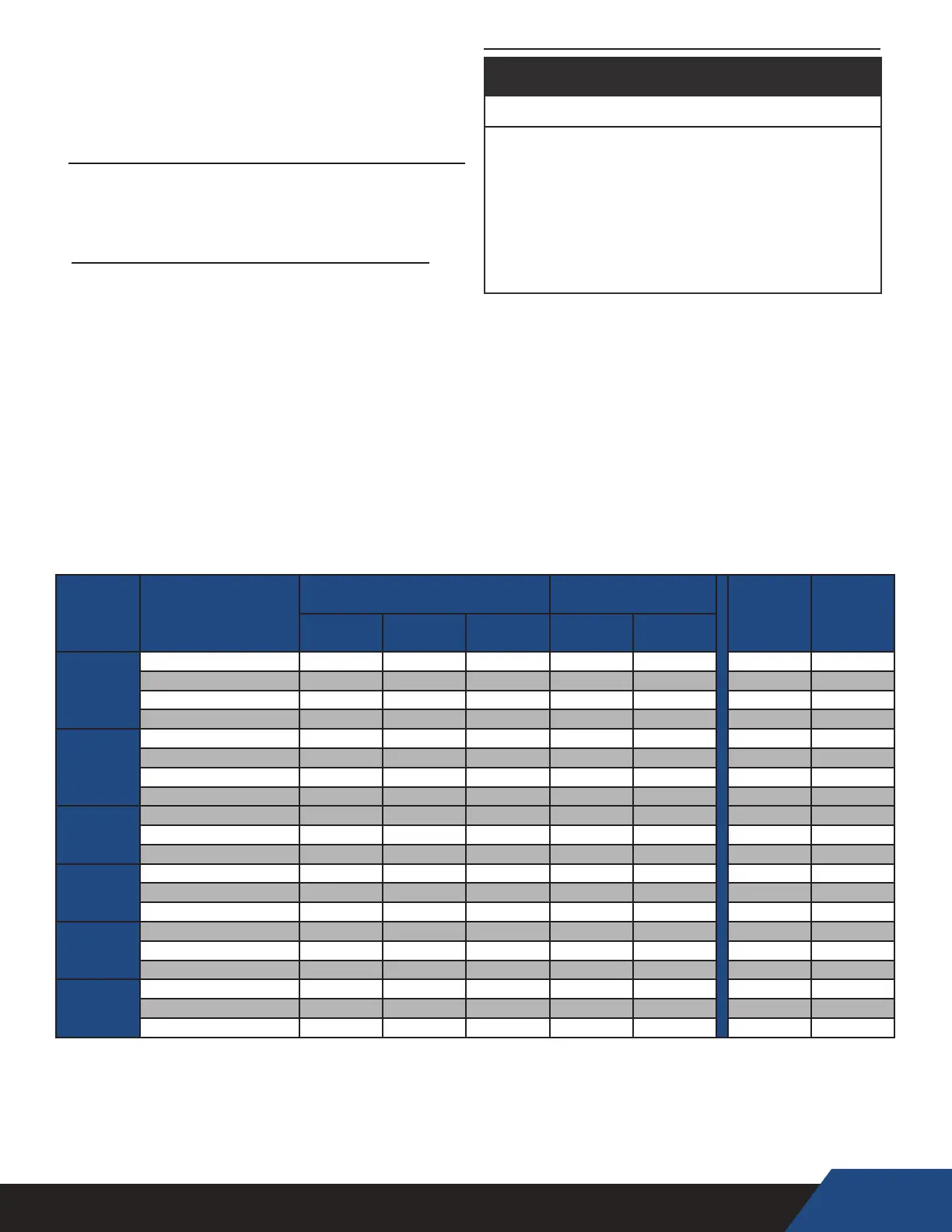
CLEARANCES
To ensure optimal performance a minimum of 36" clearance is
required from the front of the HPWH unit and any
wall obstruction. 24" is acceptable on all other sides.
C25W 208-230/1/60
17.9 73.0 25.0 16.0 22.4 40.3
208-230/3/60
10.0 63.0 14.0 9.0
12.5
22.5
440-480/3/60 5.0
31.0 7.0
4.5 6.3 11.3
C60W
230/1/60 31.0 129.0
44.0 28.2 38.8 69.8
72.7 270.0 79.0 50.6 91 164
400/3/50 72.7 270.0 79.0 50.6 91 164
C810WM 208-230/3/60 130.0 560.0 130.0 83.3 163 293
460/3/60 72.7 270.0 79.0 50.6 91 164
380-400/3/50 72.7 270.0 79.0 50.6 91 164
C1080WM 208-230/3/60 130.0 560.0 130.0 83.3 163 293
460/3/60 72.7 270.0 79.0 50.6 91 164
380-400/3/50 72.7 270.0 79.0 50.6 91 164
C1350WM 208-230/3/60 130.0 560.0 130.0 83.3 163 293
460/3/60 72.7 270.0 79.0 50.6 91 164
380-400/3/50 72.7 270.0 79.0 50.6 91 164
C1620WM 208-230/3/60 130.0 560.0 130.0 83.3 163 293
460/3/60 72.7 270.0 79.0 50.6 91 164
380-400/3/50 72.7 270.0 79.0 50.6 91 164
C1890WM 208-230/3/60 130.0 560.0 130.0 83.3 163 293
460/3/60 72.7 270.0 79.0 50.6 91 164
380-400/3/50 72.7 270.0 79.0 50.6 91 164
C2160WM 208-230/3/60 130.0 560.0 130.0 83.3 163 293
460/3/60 72.7 270.0 79.0 50.6 91 164
380-400/3/50 72.7 270.0 79.0 50.6 91 164
TABLE 2
Figure 3
Abbreviation Denitions For Table 2 Figure 3
RLA-Rated Load Amps
FLA-Full Load Amps
LRA-Locked Rotor Amps
MCA-Minimum Circuit Ampacity
MCC-Maximum Continuous Current
MFS-Maximum Fuse Size
Model Volts/Phase/HZ
Compressor PUMP
MCA MFS
RLA MCC HP FLA HP
C25W
208-230/1/60 16.0 25.0 2.5 1.4 2.5 22 25
208-230/3/60 9.0 14.0 2.5 1.4 2.5 13 15
440-480/3/60 4.5 7.0 2.5 1.4 2.5 7 10
575/3/60 3.8 6.0 3.0 1.4 3.0 7 10
C60W
208-230/1/60 28.2 44.0 5.5 1.9 5.5 38 40
208-230/3/60 20.2 31.5 6.0 1.9 6.0 28 30
440-480/3/60 9.1 14.2 6.0 1.9 6.0 14 15
575/3/60 7.1 11.0 6.0 1.9 6.0 11 15
C90W
208-230/3/60 35.3 55.0 10.0 1.9 10.0 46 50
440-480/3/60 17.9 28.0 10.0 1.9 10.0 25 30
575/3/60 11.5 18.0 10.0 1.9 10.0 17 20
C125W
208-230/3/60 48.1 75.0 13.0 4.9 13.0 65 70
440-480/3/60 21.8 34.0 13.0 4.9 13.0 33 35
575/3/60 18.6 29.0 13.0 4.9 13.0 23 30
C185W
208-230/3/60 73.1 114.0 20.0 4.9 20.0 97 100
440-480/3/60 30.1 47.0 20.0 4.9 20.0 43 45
575/3/60 24.4 38.0 20.0 4.9 20.0 36 40
C250W
208-230/3/60 90.7 127.0 25.0 2 25.0 116 125
440-480/3/60 45.7 64.0 25.0 2 25.0 59 60
575/3/60 37.9 65.0 25.0 1 25.0 49 50