22
15. All components in the hot water supply system must be
adequately sized to meet peak water ow requirement
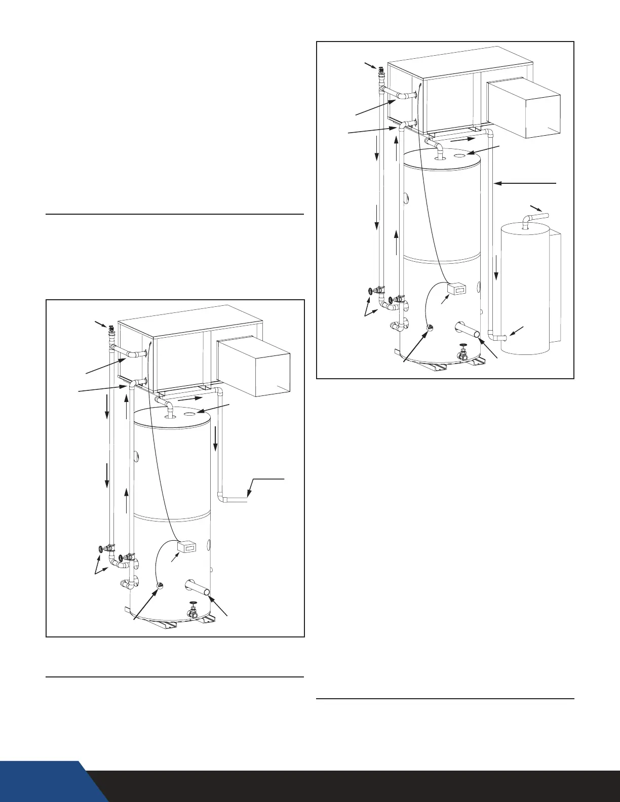
16. When the HPWH unit is installed above the storage tank
install a Tee tting at a high point in the outlet water line
leaving the unit. Install a purge valve, or if required by local
code, a T&P valve (temperature and pressure relief) in a
branch of the Tee tting that can be used to purge air from
the HPWH unit during start up. See Figure 7 and Figure 8.
17. DO NOT install a (T&P) relief valve in the outlet line of the
HPWH unit unless required by local code.
18. Dielectric unions should be installed at the inlet and
outlet water lines to the HPWH unit.
19. All HPWH water piping must be insulated.
SINGLE TANK CONFIGURATION
The HPWH must be plumbed to storage tank. The maximum
stored water temperature the HPWH unit can produce in the
storage tank is 150°F (66°C). Figure 7 shows a typical storage
tank piping conguration. Tank p orts m ust b e l arge e nough to
handle the peak water flow rates through the water heating
system. See Piping Diagrams startingon page 35 for detailed
piping diagrams.
SUPPLY
DUCT
DIGITAL TANK
THERMOSTAT
HPWH
Purge Valve or T&P
(purge air from system)
ISOLATION
VALVES
T&P VALVE
OPENING
HOT
OUTLET
REMOTE TEMPERATURE
SENSOR OR MECHANICAL
COLD
INLET
INLET
(RETURN)
OUTLET
(SUPPLY)
STORAGE
TANK
Figure 7
MULTIPLE TANK PRE HEAT CONFIGURATION
When water temperatures above 150°F (66°C) are required the
HPWH and storage tank are piped in series (upstream) with a
backup water heater. See Water Temperature on page 14. The
backup water heater will raise the temperature of the preheated
water to the nal system temperature required. Figure 8 shows a
typical preheat piping conguration.
DIGITAL TANK
THERMOSTAT
HPWH
HOT
OUTLET
STORAGE
TANK
BACKUP
WATER
HEATER
(OPTIONAL)
COLD
INLET
SUPPLY
DUCT
PRE-HEATED
WATER OUT
ISOLATION
VALVES
PRE HEATED
WATER INLET
REMOTE TEMPERATURE
SENSOR OR MECHANICAL
Purge Valve or T&P
(purge air from system)
T&P VALVE
OPENING
INLET
(RETURN)
OUTLET
(SUPPLY)
You individual HWP design may vary, Air Source as opposed to
Water Source. The same heated water piping design will apply.
HPWH
UNIT
Figure 9
STANDARD TANK THERMOSTAT
Standard tank thermostats (Aquastat) already installed in the
storage tank may be used instead of the factory supplied Digital
Tank Thermostat if desired. Ensure the standard tank thermostat
is installed the lower third of the tank. Wire the existing
tank thermostat to the HPWH terminal strip.
Individual HPWH deigns may vary. (Air source as opposed
to water source.) The same heated water piping design will
apply.
Figure 8