35
Indicator Box – indicates if the unit has been called to
run (green means run, red means on standby)
Heat Call – indicates if the master is calling units to
run to meet building demand (green means run, red
means on standby)
“TempAvg” – Tank Temperature Average: indicates
the average current tank temperature which comes
from all of the valid connected temperature probes
averaged together
“TempSet” – Tank Temperature Setpoint: indicates
the desired tank temperature to be maintained
CONFIGURATION SCREEN
“Comp HRS” – Compressor Hours: indicates the
compressor run time hours of each unit
“Tank Di Set” – Tank Dierential Setpoint: sets the
minimum tank temperature rise required to avoid
calling another unit
“System Timer” – System Timer: sets the maximum
time that the tank has to achieve the Tank Di Set
value to avoid calling another unit
“TempDi” – Temperature Dierence: sets the
dierence below the setpoint where the master will
give a call for slaves to run
“SAVE” button – Saves the “Tank Di Set” and “System
Timer” parameters
“Master IP Address” – IP Address used to connect
panel to BMS system
“Master IP Subnet” – subnet mask for address range
IP is congured in
“Master IP Gateway” – IP Address for internet router
on site used to connect to unit via VPN
ALARM SCREEN
“HIGH PRESSURE 1” – indicates if unit 1 has alarmed
out on high pressure
“LOW PRESSURE 1” – indicates if unit 1 has alarmed
out on low pressure
“COND FLOW 1” – indicates if unit 1 has alarmed out
on condenser water ow
“EVAP FLOW 1 / BLOWER 1” – indicates if unit 1 has
alarmed out on evaporator ow
“M PROTECTION 1” – indicates if unit 1 has alarmed
out on motor protection
“OIL PRESSURE 1” – indicates if unit 1 has alarmed out
on oil pressure
“ESTOP” – indicates if the Estop has been pressed
“TANK1 PROBE STATUS” – indicates if tank 1’s probe is
connected and reading valid data
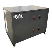
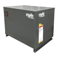
MASTER CONTROL PANEL
SETUP TO SLAVE UNITS
1) Hardwire all slave units to individual power sources
rated for the equipment with disconnects
2) Hardwire the “Master Control Panel” to a 120V
power supply through the junction box
3) Hardwire each temperature probe into the
junction box for the Master Control Panel and then
permanently attach them to their respective tanks
4) Connect all of the slave units to the router in the
junction box
5) Under the conguration screen press the “SEARCH
FOR UNITS” button to nd all of the connected slaves
(give the master controls 2 minutes to nd all of the
slave units)
6) Check the master screen to make sure that all of the
slave units are connected
MASTER CONTROLS UNIT SUPPORT
CALL SEQUENCE OF OPERATIONS
1) Set the “Tank Di Set” value to 1°F and the “System
Timer” value to 300s (5min), then press save to update
the program
2) Once the master panel determines that there needs
to be a heat call it will determine the unit call order
based on; compressor run hours, alarm status, and
unit number. Then the master will call the unit in the
rst unit in the run order to turn on
3) If the tank temperature does not increase 1°F in 300
seconds than the second unit in the run order will be
called to run