40
32
CLEANING INTERNAL INSULATION
Inspect the internal insulation on a yearly basis for any microbial
growth. The insulation never has to be cleaned unless microbial
growth is detected. If microbial growth is detected, follow the
removal steps below:
1. Disconnect all power to the unit and follow the prescribed
lock-out/tag-out procedure.
2. Wear the prescribed personal protective equipment
prescribed from the cleaning product instructions.
3. Remove as much dirt and organic material from the insulation
using a vacuum device with a HEPA lter (99.97% efcient
at 0.3 micron particles). Be careful not to tear the insulation
during the cleaning procedure.
4. Apply the microbial cleaning agent as prescribed by the
application and usage instructions.
5. Allow the unit to dry thoroughly.
6. If necessary, apply an anti-microbial agent on the insulation
per the instructions provided on the product label.
7. Discard collected microbial contaminants as required by
local or state codes.
BRAZE PLATE CLEANING INSTRUCTIONS
In some applications the heat exchanger may be subjected to
severe uid conditions, including high temperture hard water
conditions, causing accelerated scaling and corrosion rates, and
will diminish performance.
It is important to establish regular cleaning schedules, A 5%
solution of Phosphoric Acid or Oxalic Acid may be considered.
Other types of solutions can be obtained from your local
wholesaler. Make sure cleaning solution is applicable for stainless
steel and copper and all directions are followed.
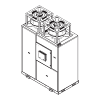
Do not heat solution. Be sure to flush heat exchanger with
fresh water after cleaning. See Figure 12.
Figure 12
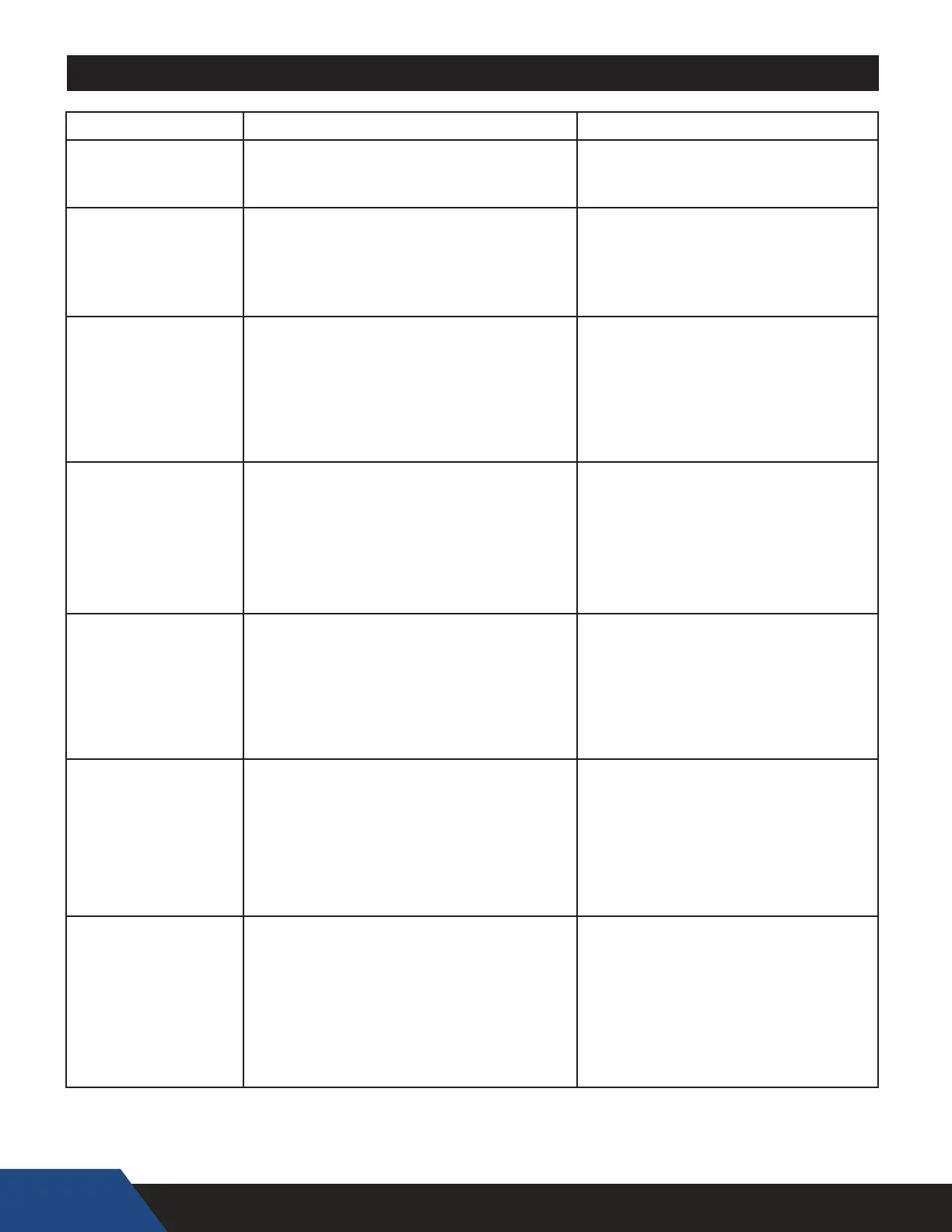
TROUBLESHOOTING
PROBLEM POSSIBLE CAUSES CORRECTIONS
Heat pump is too noisy.
1. Sheet metal fasteners are loose.
2. Operating vibration is transferring to oor or
building structure.
Tighten fasteners.
Place vibration dampeners underneath unit.
Water on oor around
the heat pump and/or
water tank.
1. Tubing, valves, or fittings are leaking.
4. Condensation forming on the bottom of unit
Repair leaks as necessary.
Shim unit to level. See installation section.
Cover bottom of unit with foam insulation.
Heat pump is not running -
electrical issues.
1. Circuit does not have adequate ampacity.
2. Short circuit or loose connection in field wiring.
3. Short circuit or loose connection in the cabinet
4. Thermostat failure.
5. Defective anti-short cycle timer.
6. Compressor burn-out.
Refer to nameplate for unit requirements.
Check eld wiring diagram. Tighten all connections.
Check for loose wiring and tighten.
Replace thermostat
Reset phase monitor
Unknown
Replace compressor (refer to compressor change-out
page)
Heat pump is not running -
high pressure fault
1. Thermostat setting too high
2. Source Water temperature over 100° F
3. Low water flow causes
A. external pump is not operating
B. piping between the heat pump and storage tank
exceeds 50 equivalent feet
C. heat exchanger has scale buildup
D. shut off valves are partially closed
Thermostat setting should not exceed 150°F.
Keep heat pump off until room temperature
is back in operating range
Low water ow corrections
replace unit pump
reduce piping or add booster pump
clean heat exchanger with a mild acid wash
open all shut off valves
Heat pump is not running -
low pressure fault
1. Source Water temperature below 40°F
2. Loss of refrigerant
Keep heat pump off until room temperature is back in
operating range
Find source of leak, repair and recharge
Water is never hot enough.
1. Thermostat setting is too low.
2. Heat pump/storage tank undersized for application.
3.
Heat pump is not properly connected to storage tank.
4. Unit cooling coil is overcooling the source water.
Set thermostat for storage tank to a higher temperature.
Increase size of storage tank or install gas or electric heater
to make up for shortfall.
Refer to field piping diagrams for recommended piping.
* Reset the heat pump by removing then restoring power to the unit at the breaker or from the manual switch. (There will be a three minute delay
before heat pump restarts.) If the heat pump cuts out again on LOW or HIGH PRESSURE, additional troubleshooting is necessary to nd the cause
DO NOT CONTINUE TO RESET THE HEAT PUMP, AS CONTINUED SHORT-CYCLING MAY STRESS OR DAMAGE INTERNAL COMPONENTS.
34
CHECKING REFRIGERANT CHARGE
Servicing of the refrigeration circuit must only be performed
by agencies or individuals possessing Type II or Universal
certification as defined in Section 608 of the Clean Air Act. See
Qualifications on page 8.
This HPWH unit is factory charged with 134a refrigerant. See the
rating label on the HPWH unit and Table 9 for refrigerant charge
by weight. It should not be necessary to add or remove refrigerant
during installation or start up. Refrigerant lost during frequent
refrigerant pressure testing can cause low refrigerant conditions.
Air and water ow should always be checked rst to eliminate
other potential problems before checking the refrigerant charge.
Check Water Temperature Rise
Always check water temperature rise through the HPWH
unit’s internal heat exchanger before checking the refrigerant
charge. See Start Up on page 29 for information on how to
measure the water temperature rise.
If the measured water temperature rise during start up was
within 8°F to 12°F (4°C to 7°C) checking the charge is not
necessary unless other conditions warrant testing.
If the measured temperature rise through the HPWH unit is less
than 8°F (4°C) checking the charge is not necessary unless
other conditions warrant testing. Short water piping runs
between the HPWH and the storage tank will produce lower
temperature rises and are not problematic.
If the measured temperature rise through the HPWH unit is
more than 12°F (7°C) check for restrictions in the inlet and
outlet water piping connected between the HPWH unit and the
storage tank.
SUPERHEAT CALCULATION
1.
2.
Measure and record the suction pressure at the
suction line pressure access port inside the unit.
Convert the recorded suction pressure to
saturated temperature.
3. Measure the suction line temperature near the suction line
pressure access port inside the unit.
4. Compare the suction line temperature to the to the saturated
temperature in Table 10.
TABLE 10
R134A SATURATED TEMPERATURE CHART
SATURATED
TEMPERATURE °F
SATURATED
TEMPERATURE °C
REFRIGERANT
PRESSURE (PSI)
0 -18 7
5 -15 9
10 -12 12
15 -9 15
20 -7 18
25 -4 22
30 -1 26
35 2 30
40 4 35
45 7 40
50 10 45
55 13 51
60 16 57
65 18 64
70 21 71
75 24 79
80 27 87
85 29 95
90 32 104
95 35 114
100 38 124
105 41 135
110 43 146
115 46 158
120 49 171
125 52 185
130 54 199
135 57 214
140 60 229
145 63 246
150 66 263
155 68 281
5. The difference between saturated temperature and suction
line temperature is the superheat. Superheat normal range
should be 8°F to 12°F (4.4°C to 6.7°C).
TABLE 9
MODEL FACTORY CHARGE R134A
C25
7#
C60
C90
C125
C185
C250
14#
20#
60#