OMC-160-3 Manual Page 11
4.6 Electrical installation
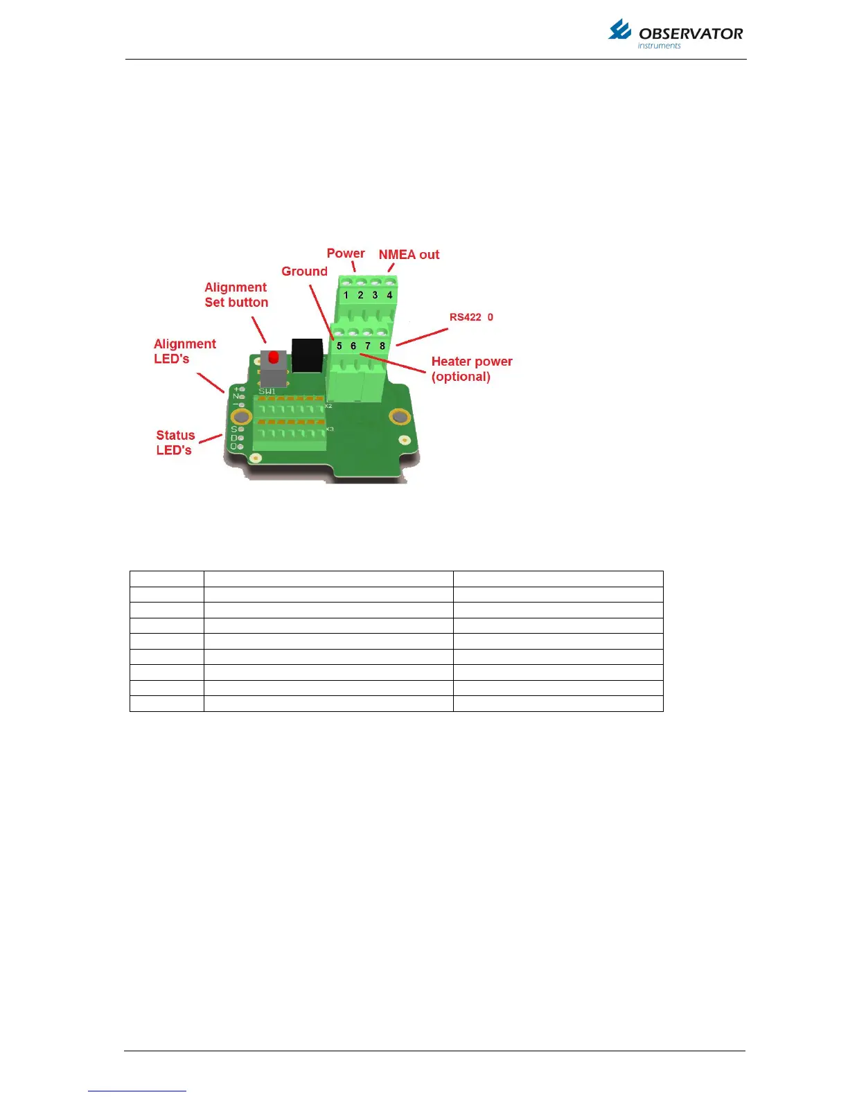
4.6.1 Connections
The OMC-160 anemometer is provided with a junction box to connect the sensor to the field cabling.
The junction box provides a M20 gland for the power & signal cable.
If the OMC-160-3 heating option is fitted, an additional M20 gland is provided for a separate cable for
24 V heater power supply.
Table 1: Connector X1
Recommended cable: shielded 2x2x0.75mm2 (like OMC-494)
Terminal 5 must be used for NMEA shield connection.
Terminal 8 is meant as 0 reference in case the receiver has a RS422 input, a separate wire should be
used and connected to the signal ground of the receiver.
Do not use terminal 8 for shield connection, this can cause an earth fault!
 Loading...