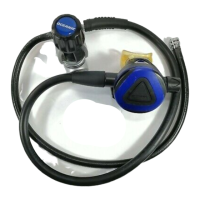
REGULATORS
DELTA II SECOND STAGE
© 2002 Design 1997
OCEANIC® Product Service Guide
Doc. 12-2223-r03 (10/3/10)
PG-3
R = Revision
TROUBLE SHOOTING
SYMPTOM POSSIBLE CAUSE TREATMENT
* Freeow or leakage present.
(Adjustment knob turned in.)
* Excessive inhalation resistance.
(Adjustment knob turned out.)
* Rattle heard inside second
stage.
* Little or no airow when purge
button is depressed.
* Adjustment knob difcult to
turn.
* Water entering second stage.
1. Trapped debris prohibiting movement of
purge button.
2. Lever arm bent.
3. Excessive intermediate pressure.
4. Damaged or worn LP seat.
5. Damaged adjustable orice.
6. Locking nut (20) overtightened onto pop-
pet shaft.
7. Washer(18) bent or distorted.
8. Adjustable orice(11) incorrectly ad-
justed.
9. Spring(16) worn or weakened.
10. Inlet coupling (12) not sufciently tight-
ened into inlet tube.
1. Locknut(20) overtightened onto poppet
shaft, causing excessive spring tension.
2. Locknut(20) insufciently tightened onto
poppet shaft, causing lever slack.
3. Lever arm bent.
4. Adjustable(17) orice incorrectly ad-
justed.
5. Insufcient intermediate pressure from
rst stage.
1. Gravel or sand trapped inside housing.
2. Lever slack present.
1. Front cover not sufciently tightened
onto housing.
2. Lever slack present.
3. Adjustable(11) orice incorrectly ad-
justed.
1. Debris or corrosion present on adjust-
ment shaft.
2. Debris present inside knob(33).
3. Debris or corrosion present on or inside
adjustment spring(27).
1. Tear in mouthpiece.
2. Exhaust valve diaphragm(6) distorted
or damaged.
3. Demand diaphragm(3) distorted or
damaged.
4. Demand diaphragm washer(2) not
present.
5. Front cover(1) insufciently tightened
onto housing.
6. Cracked or damaged housing(4).
1. Remove and clean.
2. Replace with new.
3. Refer to rst stage troubleshooting
chart.
4. Replace with new.
5. Replace with new.
6. Replace with new and readjust. (Refer
to tuning section.)
7. Replace washer, spacer, and locking
nut with new.
8. Turn in clockwise to adjust. (Refer to
tuning section.)
9. Replace with new.
10. Follow correct procedure given in
reassembly section to tighten.
1. Replace with new and readjust. (Refer
to tuning section.)
2. Tighten to correct spring load and lever
height. (Refer to tuning section.)
3. Replace with new.
4. Adjust to correct contact. (Refer to tun-
ing.)
5. Refer to rst stage troubleshooting
chart.
1. Remove and clean.
2. Tighten locking nut onto poppet shaft.
(Refer to tuning section.)
1. Tighten until perfectly snug.
2. Tighten locking nut onto poppet shaft.
(Refer to tuning section.)
3. Adjust orice to correct contact. (Refer
to tuning section.)
1. Disassemble and clean.
2. Flush out or disassemble if necessary
to clean.
3. Disassemble to clean or replace with
new as needed.
1. Replace with new.
2. Replace with new.
3. Replace with new.
4. Install new.
5. Tighten until perfectly snug and properly
aligned.
6. Replace with new.