REGULATORS
DELTA II SECOND STAGE
© 2002 Design 1997
OCEANIC® Product Service Guide
Doc. 12-2223-r03 (10/3/10)
PG-4
R = Revision
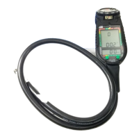
Fig. 1
DISASSEMBLY PROCEDURE
NOTE: Be sure to perform the steps outlined in the Initial
Inspection Procedures prior to disassembling the regulator.
Review the troubleshooting section to gain a better idea of
which internal parts may be worn, and to better advise your
customer of the service that is needed.
1. Snip the plastic tie wrap(8) which holds the mouthpiece(9), and
remove the mouthpiece. Inspect the condition of the mouthpiece
to ensure that it is supple and free of any tears or corrosion.
Discard if found.
2. Remove the hose from the second stage, using an 11/16" open
end wrench, while holding the hex portion of the inlet coupling(12)
secure with a 3/4" open end wrench.
3. Remove the front cover(1) to expose the diaphragm(3), using a
Delta II front cover tool if necessary, and remove the diaphragm
washer(2). Pink and black washers should be replaced with one
white washer (P/N 4590).
4. Grasp the diaphragm(3) by the raised edges of the center, and
lift with a slight upward twist to remove. Inspect the diaphragm
to ensure it is supple and free of any tears, corrosion, or other
distortion. Discard if found.
5. Depress and hold the lever arm(17) to remove the inlet coupling
(12) in a counter clockwise direction, using a 3/4" open end
wrench. (Fig. 1)
6. Remove the o-ring(13) from the inlet coupling(12) and inspect
for any signs of decay. Discard if found.
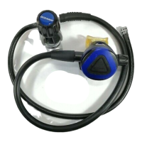
7. Using a narrow slotted blade screwdriver, remove the orice(11)
by turning it counter clockwise inside the coupling(12). When it
has disengaged completely from the threads, press it out with
the use of a cotton swab. (Fig. 2) Use caution to avoid nicking
or scratching the delicate knife edge of the orice as this is done.
Remove and discard the o-ring(10). Inspect the orice(11) care-
fully with the use of a magnier to ensure that it is perfectly free
of any scoring or nicks. If found, discard and DO NOT attempt
to reuse.
9. Turn the adjustment knob(33) out completely until resistance is
felt. Remove the adjustment knob cap screw(7) using a 5/32"
hex key and slide the knob off the adjustment shaft.
10. Remove the packing nut(32) by turning it counterclockwise using
a 5/8" open end wrench. Remove the thrust washer(31) from the
adjustment stem(29).
Fig. 2