REGULATORS
DELTA 4 SECOND STAGE
© 2002 Design, 2005
PG-10
OCEANIC® Product Service Guide
Doc. 12-2803-r02 (10/3/10)
14. Install the THRUST WASHER (31) onto the ADJUSTMENT
SHAFT (29), then slide the PACKING NUT (32) over the SHAFT
and thread it onto the ADJUSTMENT TUBE (24) until secure.
Tighten with a 5/8" open end wrench to a torque of 12 in/lbs.
CAUTION: DO NOT over tighten! Doing so will damage
the HOUSING ASSEMBLY or other parts, requiring their
replacement.
15. Install the ADJUSTMENT KNOB (33) over the ADJUSTMENT
SHAFT (29) and PACKING NUT (32). Insert the ADJUSTMENT
KNOB SCREW (34) and tighten in a clockwise direction with a
3/32" hex key to a torque of 4 in/lbs.
16. Using a Poppet Tool, push the POPPET (15) into the HOUSING
ASSEMBLY (5) to expose the WASHER (18) and SPACER (19)
inside the HOUSING ASSEMBLY. Place the Forks of the LEVER
ARM (17) over the POPPET Shaft between the WASHER and
the SPACER. Relax the POPPET and watch to ensure that the
LEVER ARM stands upright.
17. Lubricate and install the COUPLING O-RING (13) onto the SWIVEL
COUPLING (12). Install the SWIVEL COUPLING into the Inlet
Tube of the HOUSING ASSEMBLY (5) with the Smaller Opening
facing in. Tighten clockwise with a 3/4" open end wrench to a
torque of 110 in/lbs.
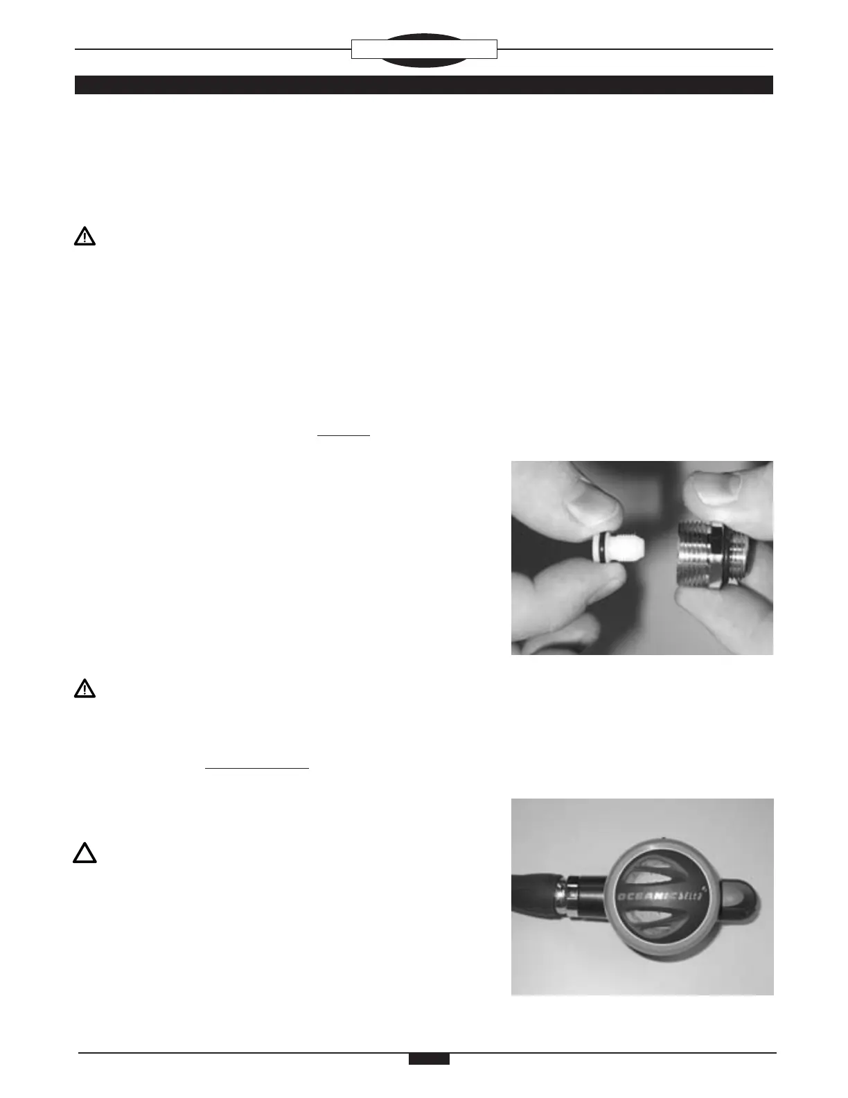
18. Lubricate and install the ORIFICE O-RING (10) onto the ORIFICE
(11). Lubricate the Threads of the ORIFICE with a very thin lm
of lubricant and insert the ORIFICE into the SWIVEL COUPLING
(12) with the Knife Edge facing in (Fig. 20).
CAUTION: Be careful to protect the delicate Knife Edge as
this is done.
19. Using a narrow shafted, slotted blade screwdriver, gently turn
the ORIFICE (11) clockwise into the INLET COUPLING (12) until
the Knife Edge is barely contacting the POPPET SEAT (14). DO
NOT continue to turn the ORIFICE any further beyond this point,
which will cause the LEVER ARM (17) to drop. Doing so will also
damage the ORIFICE Seat requiring its replacement.
NOTE: This is an important preliminary setting for the ORI-
FICE. For best sensitivity of touch, hold the screwdriver by
the shaft rather than the handle.
20. Place the DIAPHRAGM (4) inside the HOUSING ASSEMBLY (5)
with the Raised Center facing up, and ensure that it seats ush
at the Base of the Inner Threads.
21. Place the FRONT COVERS (2/3) directly over the DIAPHRAGM
(4), and ensure that they seat ush. Position the COVER RING
(1) onto the HOUSING ASSEMBLY (5), ensuring that it is correctly
seated on the Threads. Hand tighten until secure, ensuring the
Fig. 21
Fig. 20
 Loading...