REGULATORS
DELTA 4 SECOND STAGE
© 2002 Design, 2005
PG-9
OCEANIC® Product Service Guide
Doc. 12-2803-r02 (10/3/10)
7. While still compressing the POPPET SPRING (16) with the Pop-
pet Tool, insert a 1/4" nut driver through the open Adjustment
Port of the HOUSING ASSEMBLY (5) and turn the LOCK NUT
(20) further onto the POPPET (15) until 3 Threads are showing
beyond the Outer Surface of the LOCK NUT (Fig. 16 ). Remove
the Tools.
CAUTION: It is very important that a minimum of 2-3 threads
of the POPPET (15) Shaft are adjusted outside the LOCK NUT
(20). The LEVER ARM (17) may otherwise become caught on
the End of the POPPET Shaft, resulting in an uncontrolled
free ow.
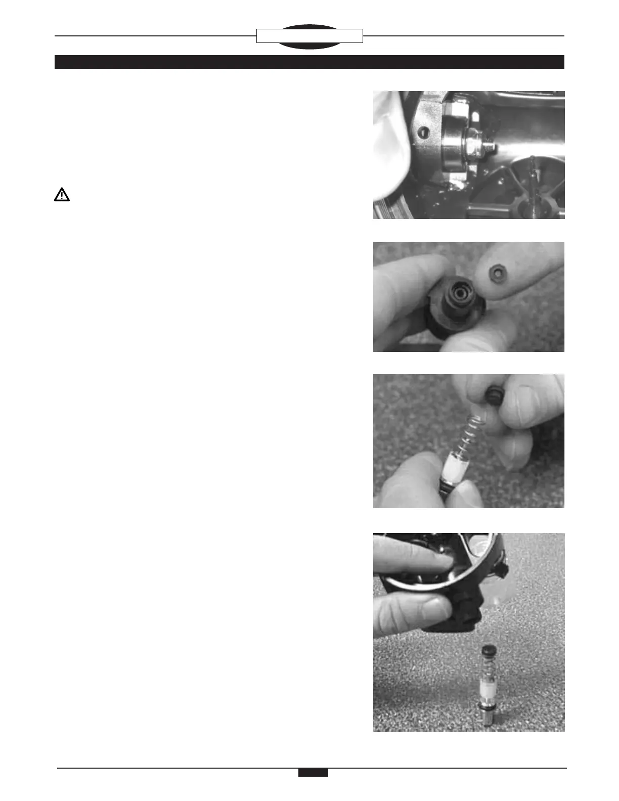
8. Lubricate and install the BALANCE SHAFT O-RING (23) into the
small opening end of the ADJUSTMENT TUBE (24). Install the
SNAP WASHER (22), smooth end down, into the ADJUSTMENT
TUBE directly over the BALANCE SHAFT O-RING, causing the
SNAP WASHER to snap securely into position. Insert the BAL-
ANCE SHAFT (21) into the small opening end of the ADJUST-
MENT TUBE through the SNAP WASHER and BALANCE SHAFT
O-RING (Fig. 17).
9. Lubricate and install the ADJUSTMENT TUBE O-RING (25) onto
the ADJUSTMENT TUBE (24). Holding the smaller end of the
ADJUSTMENT TUBE, insert it, Threaded end rst, down into the
HOUSING ASSEMBLY (5) and angle it into the ADJUSTMENT
TUBE Opening in the Side of the HOUSING ASSEMBLY. Ensure
that the ADJUSTMENT TUBE Flange mates at against the Inner
Wall of the opening. If necessary, grasp the Outer Threads and
rotate the TUBE until the surfaces mate.
10. If previously removed, install the PISTON SPRING FOLLOWER
(28) on the ADJUSTMENT SHAFT (29). Screw it on counter
clockwise, Flat Side rst. DO NOT tighten with a wrench.
11. Lubricate and install the STEM O-RING (30) onto the ADJUST-
MENT SHAFT (29).
12. Holding the ADJUSTMENT SHAFT (29) vertically, install the
ADJUSTMENT SPRING (27) over the Stem so it rests in the
Concave End of the PISTON SPRING FOLLOWER (28), then
place the SPRING PAD (26) on top with the small Rounded End
in the ADJUSTMENT SPRING (Fig. 18).
13. Holding the HOUSING ASSEMBLY (5) with the ADJUSTMENT
TUBE (24) facing down and your index nger inside pressing the
ADJUSTMENT TUBE against the Inner Wall of the HOUSING, AS-
SEMBLY, insert the ADJUSTMENT SHAFT (29), ADJUSTMENT
SPRING (27), and SPRING PAD (26) up into the ADJUSTMENT
TUBE (Fig. 19). This will push the BALANCE SHAFT (21) partially
out of the other end of the ADJUSTMENT TUBE and up against
the POPPET (15). Ensure that the BALANCE SHAFT is properly
aligned with the POPPET. Spring tension will hold the parts in
place.
Fig. 19
Fig. 16
Fig. 17
Fig. 18