REGULATORS
DELTA 4 SECOND STAGE
© 2002 Design, 2005
PG-11
OCEANIC® Product Service Guide
Doc. 12-2803-r02 (10/3/10)
FRONT COVERS are properly aligned (Fig. 21). Use the Front
Cover Tool, if necessary. DO NOT over tighten.
22. Secure the MOUTHPIECE (9) onto the HOUSING ASSEMBLY
(5) with a TIE WRAP (8), positioning the Locking Tab of the TIE
WRAP towards the Hose.
NOTE: Oceanic’s patented Orthodontic Mouthpieces are
designed to accommodate the natural overbite of the human
jaw. Ensure that it is properly positioned.
NOTE: Step 23 is ONLY FOR SWIVEL VERSION 1. If you
are working with another Version disregard Step 23 and
proceed to the next step. For Version identication see the
Exploded View Diagram.
23. With the Flat side facing down, push the LP HOSE WASHER
(39) into the Inlet of the SWIVEL COUPLING (12).
NOTE: Step 24 is ONLY FOR SWIVEL VERSIONS 1 & 2. If you
are working with a NON-SWIVEL VERSION disregard Step
24 and proceed to the next step. For Version identication
see the Exploded View Diagram.
24. Lubricate the LP HOSE O-RING (40) and place it on top of the
Swivel Ball located in the SWIVEL COUPLING (12).
NOTE: FOR SWIVEL VERSIONS 1 & 2 follow Step 25S. If
you are working with a NON-SWIVEL VERSION use Step 25N.
For Version identication see the Exploded View Diagram.
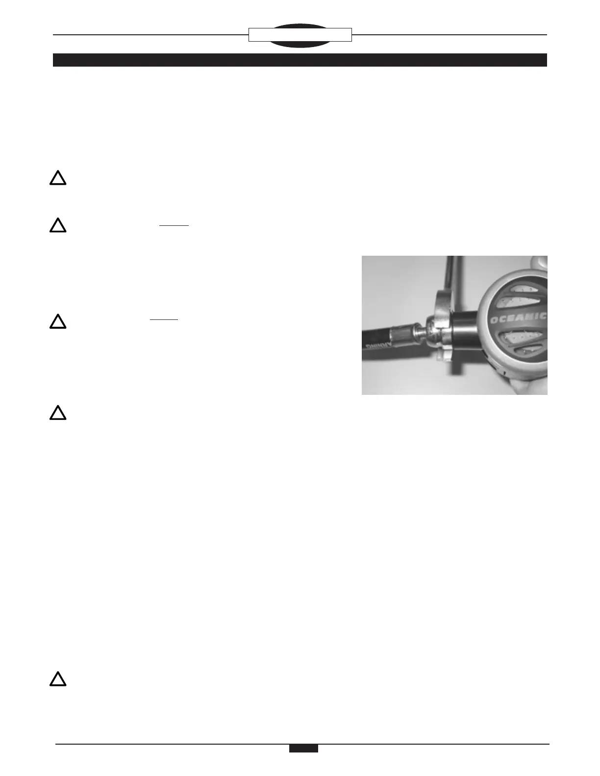
25S. While holding the Second Stage vertically with the SWIVEL
COUPLING (12, Swivel Version 1 or 47 Swivel Version 2) on top,
install the LP HOSE ASSEMBLY (38) on to the SWIVEL COU-
PLING and tighten to a torque of 55 in/lbs with an 11/16" crow's
foot wrench, while holding the Second Stage secure (Fig. 23).
25N. Hold the Second Stage, and install the LP HOSE ASSEMBLY
(45) on to the COUPLING (46) and tighten to a torque of 55 in/
lbs with an 9/16" crow's foot wrench, while holding the Second
Stage secure.
FINAL TUNING AND TESTING
FIRST STAGE TESTING
1. Perform the Leak Detection Test specied in the Initial Inspection
procedure.
NOTE: Refer to the Trouble Shooting Section to determine
the possible cause and treatment of any air leaks that may
be found.
Fig. 23