REGULATORS
DELTA 4 SECOND STAGE
© 2002 Design, 2005
PG-4
OCEANIC® Product Service Guide
Doc. 12-2803-r02 (10/3/10)
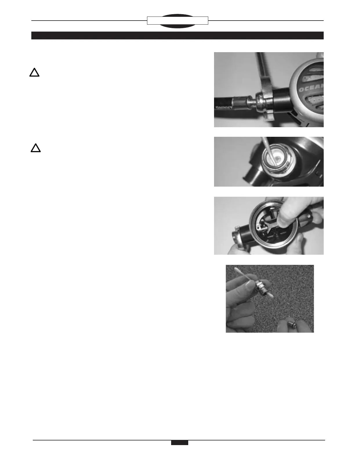
Fig. 1
DISASSEMBLY PROCEDURE
NOTE: Be sure to perform the steps outlined in the Initial
Inspection Procedures (Doc. 12-2202) prior to disassembling
the Regulator. Review the Troubleshooting Section to gain
a better idea of which internal parts may be worn, and to
better advise your customer of the service that is needed.
1. Snip the plastic TIE WRAP (8) that holds the MOUTHPIECE (9),
and remove the MOUTHPIECE. Inspect the condition of the
MOUTHPIECE to ensure that it is supple and free of any tears
or corrosion. Discard if found.
NOTE: For Swivel Versions 1 & 2 use step 2S. For Non-
Swivel Versions use Step 2N. For Version identication see
the Exploded-View Diagram.
2S. Pull the Hose Protector back and remove the LP HOSE (38) from
the Second Stage by turning it counter clockwise using a 15/16"
open end wrench, while holding the HOUSING (5) secure (Fig.
1). Remove the LP HOSE O-RING (40) and LP HOSE WASHER
(39 ONLY USED on Swivel Version 1) (Fig. 2). Discard both
and DO NOT attempt to reuse them.
2N. Pull the Hose Protector back and remove the LP HOSE (45) from
the Second Stage by turning it counter clockwise using a 9/16"
open end wrench, while holding the HOUSING (5) secure.
3. Remove the COVER RING (1), using a Front Cover Tool if neces-
sary, and remove the FRONT COVER (2) and INNER FRONT
COVER (3) to expose the DIAPHRAGM (4).
4. Grasp the DIAPHRAGM (4) by the raised edges of the center,
and lift with a slight upward twist to remove it. Inspect the DIA-
PHRAGM to ensure it is supple and free of any tears, corrosion,
or other distortion. Discard if found.
5. Depress and hold the LEVER ARM (17) to remove the SWIVEL
COUPLING (12) in a counter clockwise direction, using a 3/4"
open end wrench (Fig. 3).
6. Remove the COUPLING O-RING (13) from the SWIVEL COU-
PLING (12) and inspect for any signs of decay. Discard if found.
7. Using a narrow slotted blade screwdriver, remove the ORIFICE
(11) by turning it counter clockwise inside the SWIVEL COUPLING
(12). When it has disengaged completely from the Threads, press
it out with the use of a cotton swab (Fig. 4). Use caution to avoid
nicking or scratching the delicate Knife Edge of the ORIFICE as
this is done. Remove and discard the ORIFICE O-RING (10).
Inspect the ORIFICE carefully with the use of a magnier to
ensure that it is perfectly free of any scoring or nicks. If found,
discard and DO NOT attempt to reuse.
Fig. 3
Fig. 2
Fig. 4