EN-6 2000 Series Indicators
1.3 Overview of Parts and Controls (Cont.)
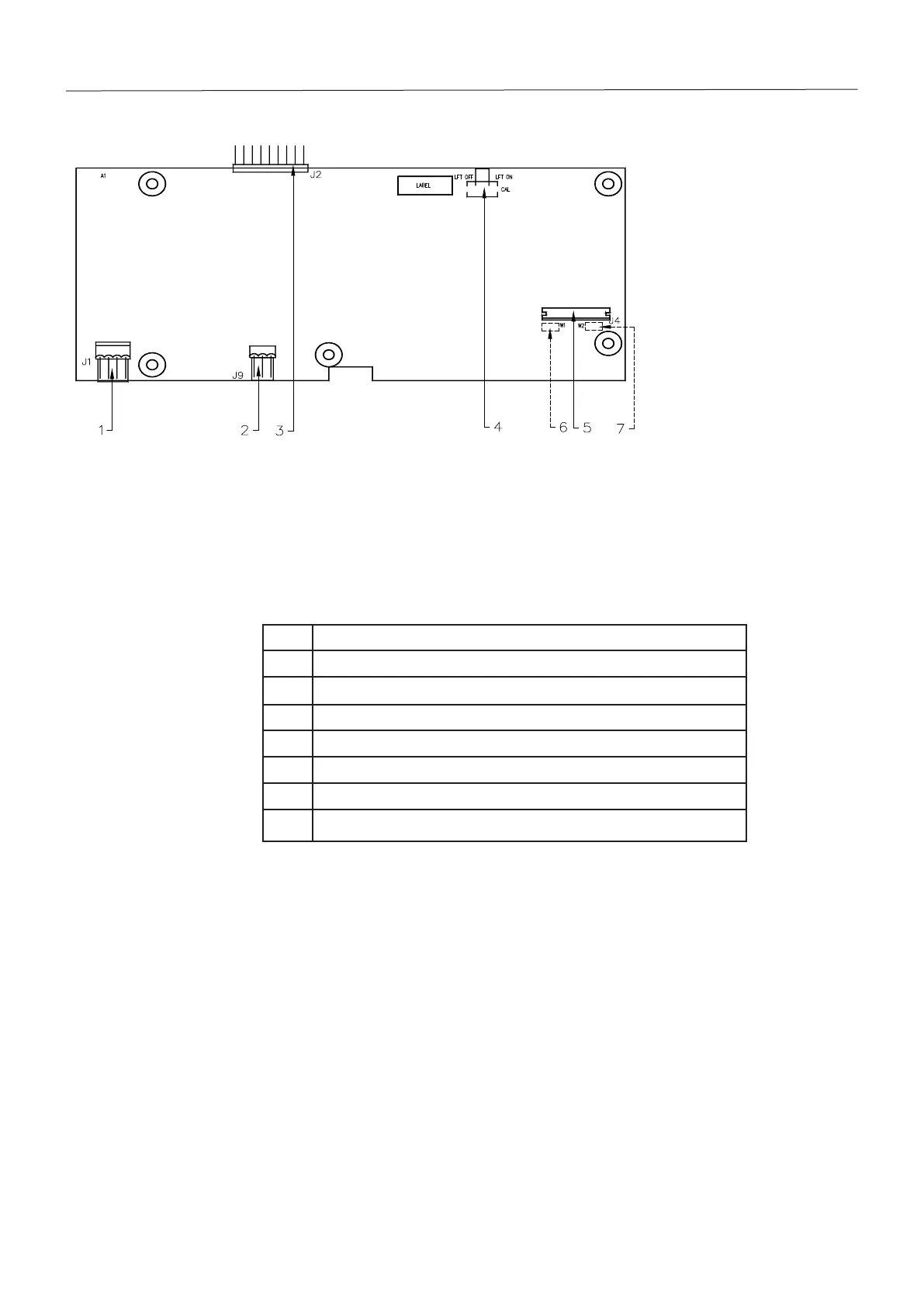
Item Description
1 Power Connector J1
2 Battery Connector J9
3 Option Connector J2
4 LFT Switch
5 4-6 Lines Sense Jumper W1 (located on the other side of PCB)
6 Load Cell Connector J4
7 4-6 Lines Sense Jumper W2 (located on the other side of PCB)
TABLE 1-2. MAIN PC BOARD.
Figure 1-2. Main PC Board.










 To Next Page