© 2016 OJ Electronics A/S
12
INSTRUCTIONS OJ-DV | Installation
Table 13.7
Power cable
Cable gland Cable diameter Cable size, min. Cable size, max. Core sleeve/stripped min.
H1/H1x M20 6-12 mm 3x1.5 mm
2
3x2.5 mm
2
10 mm
H3 M20 6-12 mm 4x1.5 mm
2
4x2.5 mm
2
10 mm
H4 M20 6-12 mm 4x1.5 mm
2
4x4 mm
2
10-15 mm
H5 M25 11-18 mm 4x2.5 mm
2
4x10 mm
2
10-18 mm
Motor cable
Cable gland Cable diameter Cable size, min. Cable size, max. Core sleeve/stripped min.
H1/H1x M20 6-12 mm 3x1.5 mm
2
3x2.5 mm
2
10 mm
H3 M20 6-12 mm 4x1.5 mm
2
4x2.5 mm
2
10 mm
H4 M20 6-12 mm 4x1.5 mm
2
4x4 mm
2
10-15 mm
H5 M25 11-18 mm 4x2.5 mm
2
4x10 mm
2
10-18 mm
A/D control cable
Cable gland Cable diameter Cable size, min. Cable size, max. Core sleeve/stripped min.
H1/H1x M20 6-12 mm 2x2x0.7 mm
2
10x2x0.7 mm
2
10 mm
H3 M20 6-12 mm 2x2x0.7 mm
2
10x2x0.7 mm
2
10 mm
H4 M20 6-12 mm 2x2x0.7 mm
2
10x2x0.7 mm
2
10 mm
H5 M20 6-12 mm 2x2x0.7 mm
2
10x2x0.7 mm
2
10 mm
Modbus round cable
Cable gland Cable diameter Cable size, min. Cable size, max. Core sleeve/stripped min.
H1/H1x M16 4-8 mm 3x2x0.7 mm
2
10x2x0.7 mm
2
10 mm
H3 M16 4-8 mm 3x2x0.7 mm
2
10x2x0.7 mm
2
10 mm
H4 M16 4-8 mm 3x2x0.7 mm
2
10x2x0.7 mm
2
10 mm
H5 M16 4-8 mm 3x2x0.7 mm
2
10x2x0.7 mm
2
10 mm
Modbus ribbon cable
H1 ... H5: Telecommunication cable/ribbon cable, 6-core, unshielded, 30 AWG/0.066 mm²
13.8 Opening the OJ-DV
• Check that the voltage supply to OJ-DV has been disconnected before opening the cover.
• Wait approx. 3 minutes after disconnecting mains voltage before removing the cover.
• OJ-DV is opened by loosening the six Torx 20 screws holding the plastic cover in place.
• Carefully remove the loosened cover.
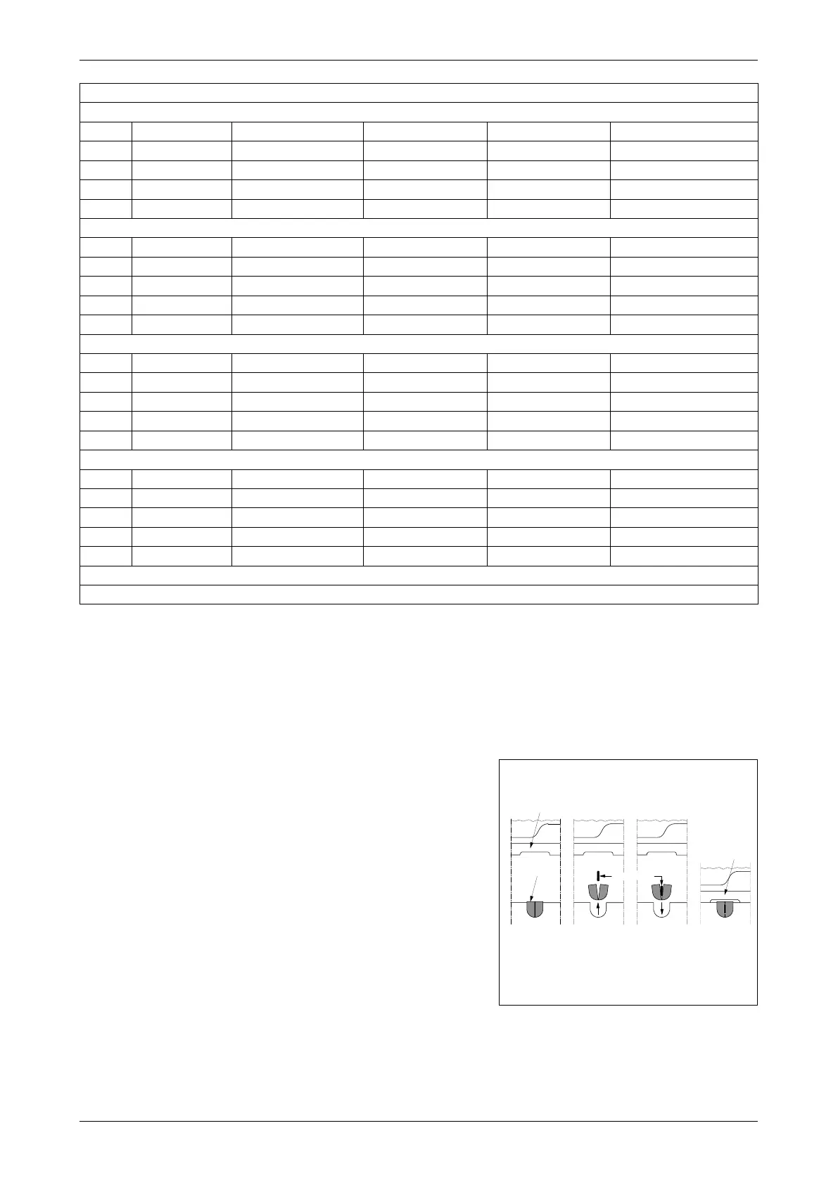
Figure 13.9
BR1014A06a
© 2015 OJ Electronic A/S
Modbus kabel
1
23
4
Gummipakning
OJ-DV låg
-DA
OJ-DV låg
BR1014A07a
13.9 Cable entries – cable glands – strain relief
• The factory-fitted cable glands should be used
when inserting power, motor and control cables into
OJ-DV.
• Remember to re-tighten the cable glands to ensure
ingress protection and strain relief.
• If Modbus communication is based on 6-core,
unshielded, 30 AWG/0.066 mm² telecommunication
cable, the cable must be inserted through the
purpose-moulded rubber seal. See fig. 13.9.
• The rubber seal has a cut insertion slit and assure
the product enclosure rating if properly fitted. See
fig. 13.9.
• The Modbus cable entry features 3-point strain
relief, which must be used.