© 2016 OJ Electronics A/S
14
INSTRUCTIONS OJ-DV | Installation
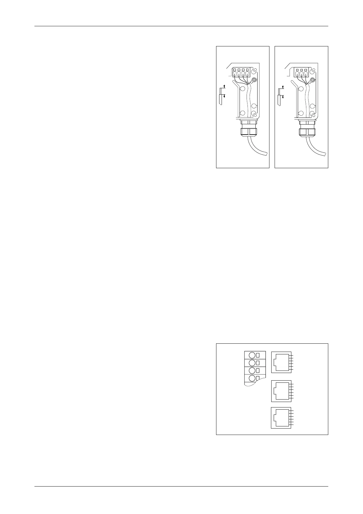
13.13 Mains voltage connection
• With 3-phase OJ-DV units, connect the power
cable to the terminals marked ”L1”, ”L2”, ”L3” and
”PE”. See fig. 13.13.1. On 1-phase OJ-DV units,
the terminals are marked ”L”, ”N” and ”PE”. See fig.
13.13.2.
• Pay special attention to section 13.6 in these
instructions, in particular:
• Earth/grounding connection must be made in one
of the following 3 ways:
• When connecting only one (1) PE conductor,
the minimum cross-section should be at least
10 mm2, or
• When connecting 2 separate ground
conductors, both should comply with the
dimensioning rules.
• If 2 conductors are used, they must be
connected to individual earth/grounding
connectors in the OJ-DV controller.
• External grounding connection. If the
machine housing is approved as a grounding
connector, then the OJ-DV can be grounded
to the machine.
• Grounding connectors must always be made
in accordance with applicable local and
international standards and directives.
• It is recommended that the PE wire is 20 mm longer
than the other wires in the cable. If the cable is
accidentally pulled out of the OJ-DV while there is
voltage on the cable and terminals, the PE wire will
then be the last to be disconnected. OJ-DV is thus
prevented from causing electric shock.
• When the stripped wire is properly inserted into the
terminal (see section 13.10), the terminal tensions
automatically with the correct torque.
• Remember to re-tighten the cable glands to ensure
ingress protection and strain relief.
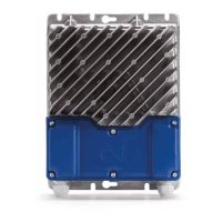
13.14 Modbus connection
• OJ-DV is equipped with four connectors for
Modbus connection.
• It also features 3 x RJ12 connectors and one strip
of spring terminals.
• On the terminal strip with spring terminals
for control signals (A/D I/O), the terminals for
connecting Modbus are marked ”Bus A”, ”Bus B”
and ”GND”. See fig. 13.14.1.
• If wanted, a round cable can be used for Modbus
communication, connected to terminals marked
”Bus A” and ”Bus B” on the OJ-DV terminal strip.
• The Modbus terminals are internally connected in
parallel to the Modbus pins in the RJ12 connectors
marked ”A” and ”B”.
• The three 3 RJ12 connectors are marked ”A”, ”B”
and ”C”.
• ”A”: Modbus connection, slave, +24 V voltage in
connector.
Figure 13.13.1
BR1014A08b
© 2016 OJ Electronics A/S
8-15mm
L1
L2 L3
PE
MAINS
BR1014A08b
Figure 13.14.1
BR1014A16a
© 2015 OJ Electronics A/S
-V+
-Add. Pin1
-Bus B
-Bus A
-Gnd
-Add. Pin2
-Add. Pin1
-Bus B
-Bus A
-Gnd
-Add. Pin2
-V+
-Gnd
-Bus B
-Bus A
-Gnd
-V+
A
C
B
+10Vdc
GND
Bus A
Bus B
-
BR1014A16a
Figure 13.13.2
BR1014A27b
© 2016 OJ Electronics A/S
L
N
PE
MAINS
12mm
BR1014A27b